Extrapolate
Extrapolate Points and Triangles
Use the Extrapolate option to extend a triangulated surface beyond the known data region. It is essential that the triangulation is a surface with a valid boundary string (i.e. the boundary string must not cross when viewed in Plan view).
This option will place a user-specified rectangle around the boundary of the triangulation. Each edge of this rectangle has a number of vertices added between its end points (the number of vertices is specified in the Number of Intervals field on the Create Bounding Box panel). The Z value of these vertices is calculated by registering the vertices onto a user-defined number of planes defined by neighbouring triangles. The number of triangles used to define the planes is specified in the registration planes field on the Create Bounding Box panel.
For a regular extrapolation save only the extrapolated triangles and then use the Interpolate option to regularise the internal triangles. Use the centroid interpolation method,do not interpolate into the boundary and do not honour breaklines.
The diagram below shows how interpolation improves the quality of an extrapolated triangulation.
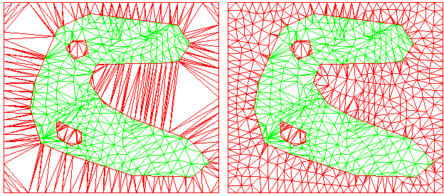
Figure 1: Interpolation of Extrapolated Triangulation
Note: To create an extrapolation to a complex polygon create the extrapolation first, interpolate into the extrapolation, and then relimit the resulting triangulation to the polygon.
Instructions
On the Model menu, point to Triangle Edit, and then click Extrapolate option
Select the triangulation. If there is only one triangulation loaded onscreen, then it will be automatically selected.
The following panel is then displayed.
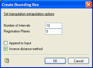
Number of Intervals
Enter the number of vertices to place along each edge of the extrapolation rectangle. This rectangle is digitised once this panel is completed. Increase this number for a more detailed extrapolation.
Registration Planes
Enter the number of triangles to use to calculate the Z value of the extrapolated points. It should be set according to the amount of data in the surface. For a better extrapolation use a larger number.
Note: Do not use a large number or registration planes for surfaces with few boundary triangles.
Append to Input
Select this check box to create a triangulation that contains all of the input triangles and the extrapolated triangles. If this is not selected, the triangulation is just the extrapolated triangles.
Inverse distance method
Select this check box to use an inverse distance weighted average to calculate the Z values of the extrapolated vertices. This slows down the calculation slightly, but gives a better result in most cases. If this check box is not selected, then the average of the registered values will be used. By using inverse distances, triangles further from the extrapolated vertex have less influence on the Z value than
Click OK.
Digitise the extrapolation rectangle. This rectangle should cover the extents to which you want to extrapolate the triangulation.
The Resultant Triangulation name panel is then displayed. This panel allows you to save the resulting triangulation.

