Create a 3D Triangulation
Use the Create option to construct a 3D triangulation from strings or polygons that represent a solid body, such as an ore body, dump or stope. Other structures that can be represented include faults, dykes and underground mine roads. 3D triangulations are used for volume calculations, block modelling, data isolation and flagging databases.
This option is very similar to the Underground > Stope Design > Create Stope option. The main difference is that the Create Stope option allows for the calculation of reserves while building the triangulation.
The Create option will take perimeters or strings displayed on the screen, of either open or closed polygons and builds triangulations between them. Polygons used for the triangulation do not have to be co-planar. You can also triangulate polygons through using the Polygons option.
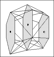
Figure 1: 3D Triangulation of Three Polygons
To achieve accurate 3D models ensure that:
- All strings are in the same direction.
- No duplicate points exist.
- Overturns do not exist in 'end plates' because they are generated using 2D triangulations.
Keep in mind that although the strings may be open or closed, open portions of a polygon will not be triangulated.
Instructions
On the Model menu, point to Triangle Solid, and then click Create to display the Create 3D Solid panel.
Note: When the panel opens, the option Create solid from design strings is enabled by default. This display the panel showing the options seen in Figure 2. When the option Create solid from surfaces is selected, the panel will display the option seen in Figure 3.
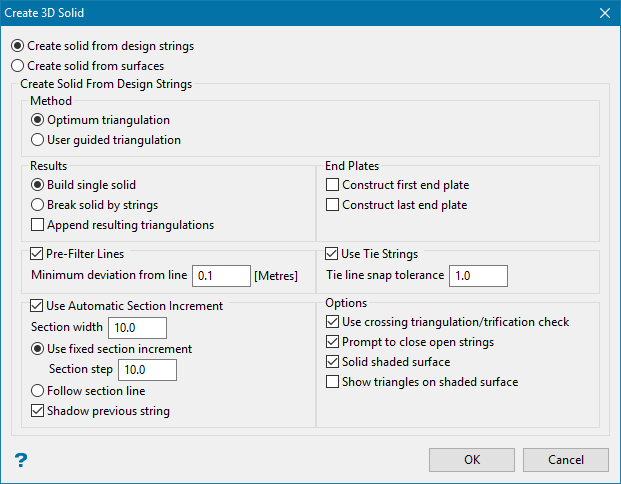
Figure 2: Panel display when Create solid from design strings has been selected.
Create solid from design strings
Select this option if you are going to create the solid from a series of strings.
Create solid from surfaces
Select this option if you are going to create the solid from triangulated surfaces. Panel is explained below.
Method
The methods correspond to 2 different algorithms of triangulating a pair of contour lines. The User guided triangulation is a little simpler, allowing you to supply links between points on 2 contours, tie-lines. Both methods try to guess tie-lines if none are given but the Optimal triangulation method goes to a bigger length optimising the calculated links using criterion of proximity.
Results
Build single solid
Use this option to create a single solid from all the polygons used to create the shape.
Break solid by strings
Use this option to name the individual sections, breaking at each polygon.

Append resulting triangulations
Use this option to create a new triangulation by adding loaded triangulations. The original triangulations are not affected. This option can be used, for example, to create a triangulation of an entire pit from the designed slope surfaces and existing topological structures (for example pavement horizon or surface topography).
See Model > Triangle Utility > Append.
Pre-filter lines
This option allows the user to reduce number of points on the polylines, thus reducing the processing time for triangulation of those polylines.
Minimum deviation from line
Enter the minimum distance between a point and the line joining the points either side of the point in question. The point will be removed if it is closer to the line than this value.
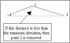
Figure 3: Minimum deviation.
Use Automatic Section Increment
Use this option to set up a section view, selecting each polygon that you want to use as you step through the section.
Using section increments does not stop you looking at the data in 3D. However, when you go back to selecting, it will return to the section on which you are working.
Select the strings/polygons to triangulate. At any time during the string selection, you can right-click to cancel and access the Create toolbar which contains picking preferences.
If you chose to build multiple triangulations, i.e. you selected the Break solid by strings option, then you will be prompted for the name of the triangulation as well as the triangulation colour.
The Create toolbar is then displayed.
The displayed toolbar will allow you to change the picking method. The contents of the Create toolbar will change once an option has been selected and used i.e. a 3D Create section will be added.

Complete
Select this option to use all of the points on the next selected string to create the triangulation.
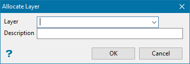
Polygon
Select this option to digitise a polygon while building the solid. You will need to assign a layer.
Partial
Select this option to specify the start and end points of a selected string. Thus separating a string into two sections. Once selected, a part of the string will be highlighted and you will need to specify whether or not you want to triangulate this part or the remaining section. This option is useful when triangulating bifurcating ore bodies (sometimes referred to, in 3D modelling, as trouser legs).

Figure 4: Partial Picking Method
Line
Select this option to digitise a line to which you want to join triangles.
Multiple
Select this option to triangulate a layer of polygons rather than selecting each polygon for inclusion. The system will determine the order of the polygons in the layer and build the solid in one pass. Checks for crossing triangles are carried out automatically.
This option will only work if the polygons progress in a common direction.

Figure 5: Picking Multiple Strings
Point
Select this option to select a point to which to triangulate.
Translate
Select this option to copy and translate existing polygons. You will need to specify the layer in which to place the translated polygons.
The Translate Polygon panel will also be displayed.
![]()
Distance to Translate
Enter, in world co-ordinates, the distance between the selected polygon and the translated (new) polygon.
Translation Mode
Orthogonal Projection
Select this option to translate the polygon perpendicular to the plane of the original polygon and away from the previous triangulation.
Enter Translation Projection
Select this option to enter the bearing and plunge of the translation.
Calculate Translation Projection
Select this option to define the translation as the vector joining the centroids of the two previously selected strings.
Colour of Translation
Select the colour of the new polygon.
Select OK.
Section width
This is the depth of view for each section. Objects outside of this parameter will be seen unless you choose to view them as shadowed objects.
Use fixed section increment
Section step
Enter the distance that is moved each step when moving the section through space. To move the section through space, use the Slice Forward ![]() or Slice Backwards
or Slice Backwards ![]() icons on the Slice toolbar.
icons on the Slice toolbar.
Alternatively, you can also select the Align View With Current Slicing Plane icon ![]() on the Slice toolbar and use the up and down arrows to move through space.
on the Slice toolbar and use the up and down arrows to move through space.
Follow section line
Use an polyline as a section guide. The sections will be displayed perpendicular to the first segment of the line.
Shadow previous string
Select this check box to shadow the data that falls outside the section.
If you select Use Tie Strings, then the Select By panel displays. From this box, choose the method of selecting the tie strings and select the tie strings.
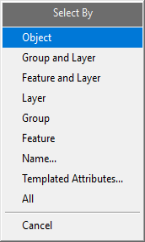
Click the attribute or attribute combination that you want to select by on the Select By menu that displays.
You can exit the Select By menu at any time by right-clicking or clicking Cancel on the Select By menu.
- Object - Click on the object(s) that you want to use to cut the triangulation. When you finish selecting objects, right-click to return to the Select By menu.
- Group and Layer - Click on an object that is part of the group and layer combination that you want to use to cut the triangulation. Click the Group and Layer combination from the Confirm menu that displays, or click Try again to select a different combination. When you are finished selecting combinations, right-click to return to the Select By menu.
- Feature and Layer - Click on an object that is part of the feature and layer combination that you want to use to cut the triangulation. Click the Feature and Layer combination from the Confirm menu that displays, or click Try again to select a different combination. When you are finished selecting combinations, right-click to return to the Select By menu.
- Layer - Click on an object in the layer that you want to use to cut the triangulation. Click the Layer name from the Confirm menu that displays, or click Try again to select a different layer. When you are finished selecting layers, right-click to return to the Select By menu.
- Group - Click on an object in the group that you want to use to cut the triangulation. Click the Group name from the Confirm menu that displays, or click Try again to select a different group. When you are finished selecting groups, right-click to return to the Select By menu.
- Feature - Click on an object that has the feature that you want to use to cut the triangulation. Click the Feature name from the Confirm menu that displays, or click Try again to select a different feature. When you are finished selecting features, right-click to return to the Select By menu.
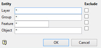
- Name - Enter any combination of Layer, Group, Feature, and Object names that you want to select. To include all names for a particular attribute, enter an asterisk ( * ) for that attribute. If you want to exclude a layer, group, feature, or object by name, click the Exclude check box next to the name. Click OK to save selections, and then click Cancel to return to the Select By menu.
- All - Click All to select all objects.
End Plates
Use this option to close off a solid triangulation by triangulating the two end polygons of the solid.
Use Tie Strings
Tie strings allow more control in defining how the shape will be created.
Important: Tie strings must be digitised in the same direction.
If you check the Use automatic section increment check box, then the Plane definition panel displays when the OK button is clicked on the main panel.
Plane Definition panel
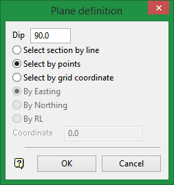
Dip
The dip is the angle of the section from horizontal. Valid dip angles are between -90° and 90°.
Select section by line
Select this option to define the plane by selecting an existing line and specifying the dip.
Only design strings may be picked and it is not possible to pick a line in an underlay. The direction of the view, and therefore the direction of the stepping, depends on the digitised sequence of the line. The digitised sequence of the line can be reversed using the Design > Object Edit > Reverse option.
Select by points
Select this option to define the plane by digitising two points and specifying the dip.
To locate a point precisely, use the Snap to Objects or Snap to Points modes (on the Digitise toolbar). Points may be snapped onto underlays, such as block model slices or triangulations. If you use Indicate mode to select the points, then the points have the current default Z value.
Select by grid coordinate
Select this option to define the plane by using a specific grid coordinate. The grid co-ordinates can contain up to three decimal places. To achieve the best results for the following three methods, we recommend using the Zoom Data Extents icon (on the Graphics toolbar) in order to view all of the graphics.
- By Easting - Select this option to enter a specific Easting value (X value).
- By Northing - Select this option to enter a specific Northing value (Y value).
- By RL - Select this option to enter a specific RL value (Z value).
Click OK.
For each translation mode listed above, the polygon will be highlighted and you will be asked whether or not to accept the translation. Accept Translation creates the translated polygon as an object in the nominated layer. This will then be treated as the next object to which to triangulate.
With Orthogonal projection, an additional option to reverse the direction of the translation is offered in the above confirm box.
Cancel
Select this option to exit the option. You will be prompted as to whether or not you want to save the changes.
Create solid from surfaces
This option allows you to build solids defined by two surfaces working in plan view. The surfaces are assumed to be two successive topographies. The solids between them correspond to Cut and Fill solids. There is no constraint on surface sizes or mutual position apart from the overlap in plan view.
Tip: For the best result, the surfaces should be consistent and have no crossing triangles.

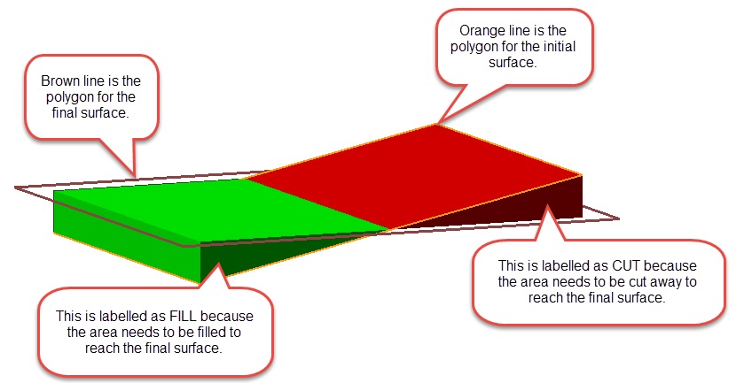
Initial and final surfaces
The initial surface is the surface you are starting with, and then filling (or cutting) toward the final surface. The new solid will include all areas between the initial and final triangulations. However, any area that is above the final surface will be labelled as fill, and any area that is below the final surface will be labelled as cut.
Attempt to repair faulty input triangulations
If the input surfaces have some inconsistencies or have crossing triangle, you may opt to repair them using. If the re-triangulation is successful, the result of the re-triangulation is saved in the file <inputFileName>_reTri.00t. The result of the re-triangulation will used to build the solids instead of the corresponding faulty input. If the re-triangulation result cannot be repaired, the original triangulation is used.
Remove small fragments
Use this to remove small sections that are below the threshold volume limit.
Projection Direction
Select the orientation based on the three choices. Vertical will be oriented in plan view. The other two are based on whether you want to project the orientation perpendicular to the initial surface or the final surface.
Holes
Preserve holes
If there are holes in the surface triangulations, then this option will create the new solid keeping the holes.
Fill holes
This option will attempt to fill in any holes that are present in the surface triangulations.

