Multi-Boolean
Use this option to use a collection of surface triangulations to split nominated triangulation solids. The cutting triangulations to be used can either be created through a previous Vulcan session or they can be dynamically created through this option.
Instructions
On the Model menu, point to Triangle Utility, then click Multi-Boolean.
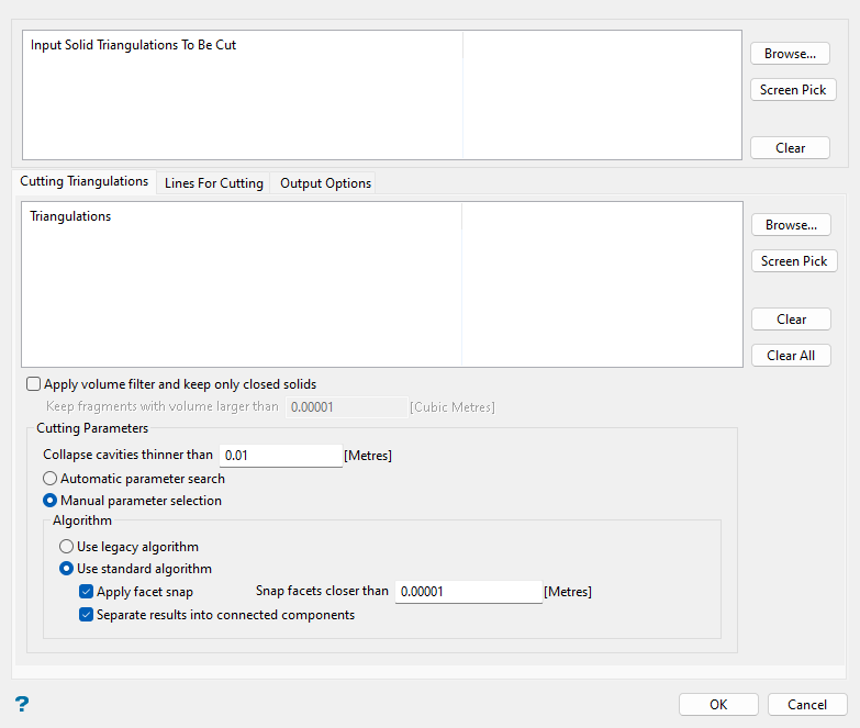
In this panel, select the original triangulation(s) to be cut with the Multi-Boolean option in the Input Solid Triangulations To Be Cut section with the Browse... or Screen Pick options. Use Browse... to select a triangulation file from a folder location. Alternatively, click Screen Pick to select from triangulations currently loaded onto the screen. If you would like to remove a triangulation file from the list, select the triangulation and click Clear.
Note: You will need to load triangulations to the Vulcan workspace prior to selecting the Multi-Boolean option if you would like to use the Screen Pick feature.
Cutting Triangulations tab
The Cutting Triangulations tab allows you to select surface triangulations that will be used for cutting in the Multi-Boolean process.
Follow these steps:
-
Choose the surface triangulations that will be used to cut the selected solid triangulation(s) in the Cutting Triangulations section.
Click Browse... to select triangulation files from a folder location.
Alternatively, click Screen Pick to select from triangulations currently loaded onto the screen.
Select a triangulation from the list and click Clear to remove the triangulation file from the list, or click Clear All to remove all triangulations from the Cutting Triangulations list.
Note: This section will also list the surface triangulations generated through the Lines For Cutting tab of the Multi-Boolean panel.
-
You can select OK at this point to create the new triangulation solids cut by the nominated surface triangulations with the Multi-Boolean option, or continue with the following steps to set optional features.
Note: If none of the options at the end of this section are selected, the Boolean algorithm will attempt to split the source solid into individual connected components with default settings. If the source triangulation is not a solid, the results will be the intersection of all source triangulations. The option will not attempt to ensure closure of the results.
-
Select the Apply volume filter and keep only closed solids checkbox to retain only triangulations larger than a specified volume. If you select this option, you must specify the minimum volume in the Keep fragments with volume larger than field. If a volume limit is set, the Boolean algorithm will attempt to close all triangulation results and return only closed triangulations. Set this parameter to
0if it is critical to have no modification to the output solid results.ExampleSee the following graphic with a solid to be cut by multiple intersecting planes:
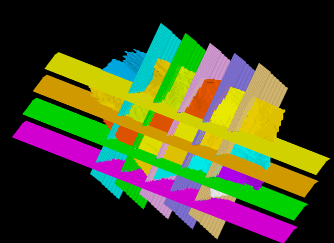
In the next graphic, notice small volumes produced at the intersections of the sectioning planes. These small volumes are artifacts of the Boolean operation and are not expected to be useful for the analysis.
In order to prevent these small volumes from being created, set the limiting volume to a non-zero value (e.g. 0.01).
-
Set the tolerance threshold for the Collapse cavities thinner than field. Cavities below the threshold entered in this field will be removed.
-
Choose between the Automatic parameter search or the Manual parameter selection options, as described below:
-
Automatic parameter search: Select this option to automatically select parameters for cutting valid solids or surfaces ensuring generation of valid output solids.
Note: The option is intended to work with only valid input solids and surfaces. A warning will appear if any input is invalid. You may choose to proceed with invalid solids and get desired result if invalid areas are far from the areas of the intersection of the input triangulations.
-
Manual parameter selection: Select this option to manually set parameters for cutting triangulations and select either Use legacy algorithm or Use standard algorithm:
-
Use legacy algorithm: Select this option to use an older algorithm to resolve Boolean operations. This is mainly for clients with projects that have been using this function with the older algorithm and wish to maintain consistency in results.
Note: The updated algorithm is more accurate and offers more features than the previous one and should be used if possible.
-
Use standard algorithm: Select this option to use the updated algorithm with additional available features.
Select the Apply facet snap checkbox if the source and intersecting triangulations have many surfaces that are nearly coincident. For example, if a pit with benches is intersected with bench surfaces, then the process may fail if nearly coincident surfaces are not considered. If this option is selected, you must specify the tolerance in the Snap facets closer than field.
Note: It is not recommended to use tolerances larger than
0.001.If the Apply facet snap checkbox is selected, you may select the Separate results into connected components checkbox to split resulting disconnected volumes into separate triangulations. By default, the Multi-Boolean process uses different calculation paths and produces aggregated triangulations, possibly resulting in triangulations consisting of multiple disconnected volumes.
-
-
-
Continue to the Lines For Cutting and the Output Options tabs of the panel to optionally change the default settings in these sections.
Lines For Cutting tab
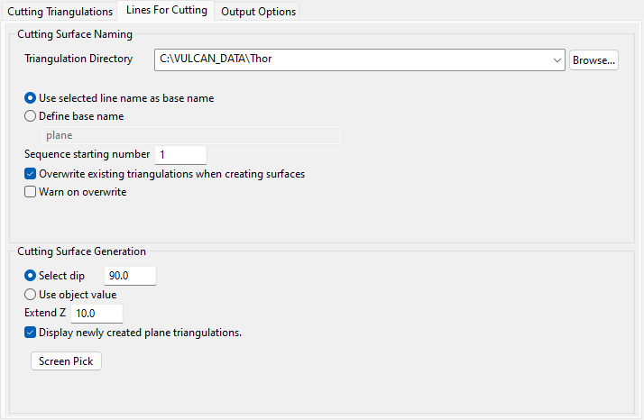
The Lines For Cutting tab allows you to dynamically create the surface triangulations from lines loaded on screen that will be used for cutting in the Multi-Boolean process.
Follow these steps:
-
Select the Triangulation Directory that will be used to store the resulting surface triangulations. Leave this field blank if you want to save the resulting triangulations within your current working directory. Use the Browse... button if you want to nominate a different storage location.
To save your triangulations within an existing triangulation database, use the Browse... button to locate the applicable (
.tri) folder. Once found, click on the folder before clicking OK. -
Specify the base name of the lines to be used for cutting in this section by selecting either Use selected line name as base name or Define base name.
-
Use selected line name as base name: Select this option to use the name of the original selected line object as the base name when naming the resulting surface triangulations.
If the chosen line object is named
LINE_1, and a sequence starting number of1has been specified, then the resulting triangulations will be namedLINE_11.00t,LINE_12.00t,LINE_13.00t, etc. -
Define base name: Select this option to enter a base name for the resulting surface triangulations.
If you enter a base name of
MyLine_, and a sequence starting number of1has been specified, then the resulting triangulations will be namedMyLine_1.00t,MyLine_2.00t,MyLine_3.00t, etc.
-
-
Enter the Sequence starting number. The specified value will be incremented by one and appended to the end of the base name for each of the resulting surface triangulations.
NoteThe following naming convention is used when naming the resulting surface triangulations:
<base name><sequence number>.00t -
Select the Overwrite existing triangulations when creating surfaces checkbox to overwrite, or replace, the existing triangulations that happen to share the same name as the resulting triangulations. If this option is enabled, you may select the Warn on overwrite checkbox to be warned when an existing triangulation is about to be replaced.
Confirming the replacement when prompted, that is, selecting the Yes button, will result in the replacement of all existing triangulations that happen to share the same name. If you select the No button, then Vulcan will increment the specified sequence number until a unique triangulation name is found.
If you choose not to overwrite existing triangulations and if triangulations
MyLine_1.00tandMyLine_2.00talready exist, then the triangulation names ofMyLine_3.00tandMyLine_4.00twill be assigned. -
Select whether to Select dip or Use object value for Cutting Surface Generation.
-
Select dip: Select this option to assign a dip value to the resulting surface triangulation.
-
Use object value: Select this option to use the line object's object value, which is defined through the Z field of the Status toolbar when the object is initially created, as the dip value for the resulting surface triangulation. Use the Design > Attribute Edit > Value option to modify an object's object value.
-
-
Enter a value for the Extend Z field. This entry specifies the distance in the Z direction to extend the generated surface beyond the Z extents of the chosen solid triangulation(s) to be cut.
-
Select the Display newly created plane triangulations checkbox to display the resulting surface triangulations as soon as they have been generated.
-
Click Screen Pick to select a line object and generate the surface triangulations. Once selected, the panel will temporarily collapse and you will be prompted to select the necessary line objects from the screen via the Select By dialog box.
Note: Generated surfaces are automatically added to the list in the Cutting Triangulations section.
Output Options tab
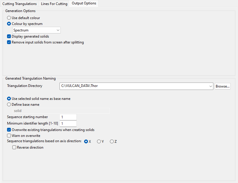
The Output Options tab allows you to define the display attributes, storage location, and naming conventions for the resulting triangulations.
Follow these steps:
-
Select between Use default colour and Colour by Spectrum under the Generation Options section.
-
Use default colour: Select this option if you want the default colour to be used when colouring the resulting triangulations. The default colour is specified through the Status toolbar.
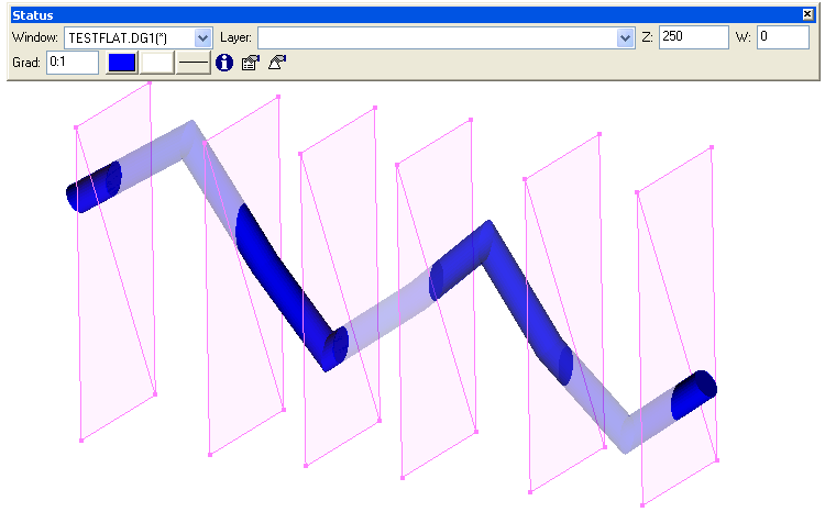
ExampleIn the following diagram, the original triangulation solid has been split into seven separate triangulations with the default colour (dark blue) being used to colour each of the resulting triangulations.
-
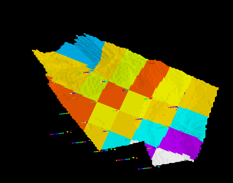
Colour by spectrum: Select this option to colour the resulting triangulations by spectrum. The colour spectrum is stretched over the axis values. Use the drop-down list to select the desired spectrum.
ExampleIn the following diagram, a spectrum was used to colour resulting triangulations.
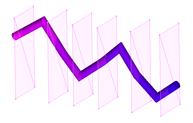
If you select the Between two RGB values option from the drop-down list, you will need to nominate two colours to stretch over the axis values of triangulations. For example, if you select red and blue, then the small values would be red, the middle values purple, and the large values blue. The colour of the middle values is an average of the two chosen colours.
-
-
Select the Display generated solids checkbox to display the resulting triangulation solids onscreen after the Multi-Boolean process has run.
-
Select the Remove input solids from screen after splitting checkbox to remove the original solid triangulation from the screen after the Multi-Boolean process has run.
-
Select the Triangulation Directory that will be used to store the resulting triangulations from the drop-down list in the Generated Triangulation Naming section. Leave this field blank if you want to save the resulting triangulations within your current working directory. Use the Browse... button if you want to nominate a different storage location.
To save your triangulations within an existing triangulation database, use the Browse... button to locate the applicable (
.tri) folder. Once found, click on the folder before clicking OK. -
Specify the base name of the resulting triangulations by selecting either Use selected solid name as base name or Define base name.
-
Use selected solid name as base name: Select this option to use the name of the original selected solid as the base name when naming the resulting triangulations.
If the original triangulation solid is named
TOPO.00t, and a sequence starting number of1has been specified, then the resulting triangulations will be namedTOPO1.00t,TOPO2.00t,TOPO3.00t, etc. -
Define base name: Select this option to specify the base name for the resulting triangulations.
If you specify a base name of
MyTopo_, and a sequence starting number of1has been specified, then the resulting triangulations will be namedMyTopo_1.00t,MyTopo_2.00t,MyTopo_3.00t, etc.
-
-
Enter the Sequence starting number. The specified value will be incremented by one and appended to the end of the base name for each of the resulting triangulations.
NoteThe following naming convention is used when naming the resulting triangulations:
<base name><sequence number>.00t -
Enter the Minimum identifier length for the number of digits to use in the name of resulting triangulations.
If the original solid name was
bmf50x50.00t, the new name would becomebmf50x501.00twith a Minimum identifier length of1. It would becomebmf50x500000000001.00twith a length of 10. -
Select the Overwrite existing triangulations when creating solids checkbox to overwrite, or replace, the existing triangulations that happen to share the same name as the resulting triangulations. If this option is enabled, you may select the Warn on overwrite checkbox to be warned when an existing triangulation is about to be replaced.
Confirming the replacement when prompted, that is, selecting the Yes button, will result in the replacement of all existing triangulations that happen to share the same name. If you select the No button, then Vulcan will increment the specified sequence number until a unique triangulation name is found.
If you choose not to overwrite existing triangulations and if triangulations
MyTopo_1.00tandMyTopo_2.00talready exist, then the triangulation names ofMyTopo_3.00tandMyTopo_4.00twill be assigned. -
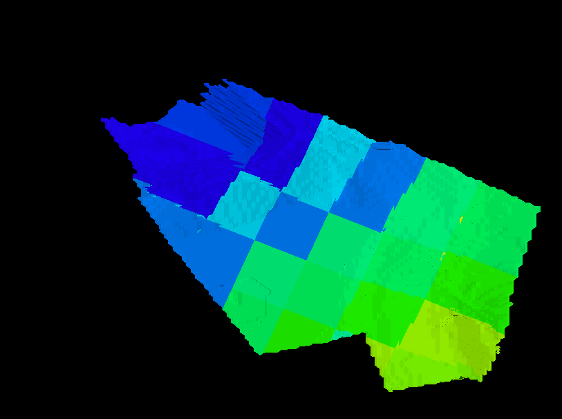
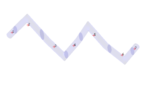
Nominate an axis direction (X, Y, or Z) for the Sequence triangulations based on axis direction option to sort and sequence the generated solids by. After splitting the original triangulation solid, Vulcan will calculate the centroid position for the new triangulations before using the centroid values (X, Y, or Z) to name the triangulations.
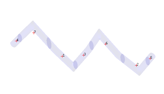
ExampleIn the following diagrams, the original triangulation solid has been split into seven separate triangulations.
If the X axis value was used to sort and sequence the resulting triangulations, then the triangulations would be named in the following order:
If the Y axis value was used to sort and sequence the resulting triangulations, then the triangulations would be named in the following order:
Select the Reverse direction checkbox to reverse the direction in which solids are sorted along the X, Y, or Z axis.
After completing the Cutting Triangulations, Lines For Cutting, and Output Options tabs of the panels as desired, click OK to run the Multi-Boolean option or click Cancel to discard the changes to the panel and exit.
When you click OK, the Multi-Boolean option will run and the resulting triangulations will be created.

