Set Up
Specify Blast Defaults
The Set Up option to select the site, deposit and general blast hole pattern parameters for the blast to be designed or edited.
The sites and deposits available must have been defined in the
blastdes.spc
file, which resides in the
$ENVIS_RESO
area. Also defined in this file are corresponding defaults, such as datum level and bench height.
Instructions
- Select Open Pit menu
- Select Blast Design Bench submenu
- Select Set Up option
Select the required site (defined in the
blastdes.spc
file) from the list.
Select the required deposit.
![]() Note
Note
You won't be prompted to select a site or deposit if only one site/deposit has been defined in the
blastdes.spc
file. If this is the case, then the deposit design file will be automatically opened.
The following panel is then displayed.
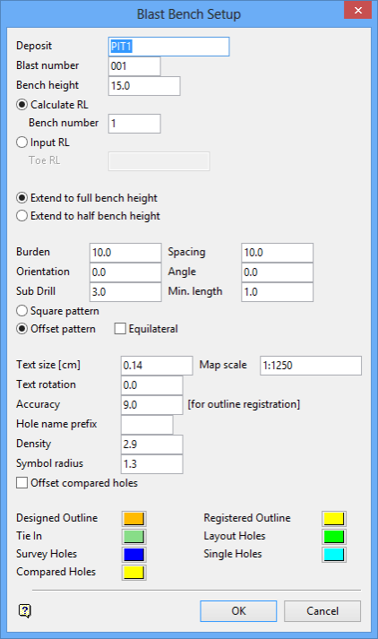
Blast Bench Setup panel
Deposit
This shows the name of the deposit selected in the previous step. It can be overwritten, in which case it must be another existing deposit.
Blast number
The blast (and bench) number are used to create the layer name of the blast outline and the layer name of the blastholes. The layer name for the outlines is
<bench number>_<blast number>_BD
and the layer name for blastholes is
<bench number>_<blast number>_HO
.
Bench height
Enter the bench height. The default value is the height set in the .spc file.
Calculate RL
Select this option to calculate the nominal RL from the datum level, bench number and bench height. The default Z value is then set to the calculated value. Alternatively, you can select the Input RL option, which to set the toe elevation by specifying the Z value.
Bench Number
Enter the bench number. This number in conjunction with the blast number will be used to create the layer names of the outlines and blastholes.
Input RL
Select this option to specify the nominal toe RL.
Toe RL
Enter the toe RL. The integral bench number will be calculated from this value and the datum level and then will be used in conjunction with the blast number to create the layer names of the outlines and blasts.
Extend to full bench height/Extend to half bench height
Select Extend to full bench height to produce holes that start at the bench toe RL and extend the full bench height up to form the collars at the top of the bench.
Select Extend to half bench height to produce holes that start at the bench toe RL and extend a half bench up to form collars at a mid bench surface.
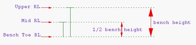
Diagram 1 - Upper RL/Mid RL
Burden
Enter the distance between adjacent rows in a pattern.
Spacing
Enter the distance between adjacent holes in a row.
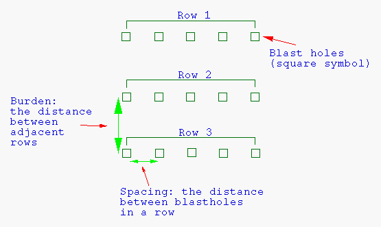
Diagram 2 - Burden, Spacing, Square Pattern
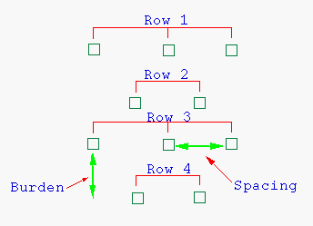
Diagram 3 - Burden, Spacing, Offset Pattern
Orientation
Enter the orientation of the blastholes, which must be between 0 - 360 degrees. This is the bearing of an angled hole.
Angle
Enter the hole angle, which must be between 0 - 90 degrees deviation from vertical. This is NOT the dip of the hole, 60° is a down hole of 30° dip.
Sub Drill
Enter the depth to which a blast hole will be drilled below the toe of the bench. This is the vertical depth of extra drilling.
Minimum drilling length
Enter the minimum drilling length. Any hole with a length less than this will not be created.
Square Pattern
Select this option to create a square layout (see Diagram 2). Alternatively, select the Offset Pattern option to create a staggered layout.
Offset Pattern
Select this option to create a staggered layout (see Diagram 3).
Equilateral
Select this check box to use the equilateral pattern on the staggered layout. The spacing is used to determine the length of the triangle side.
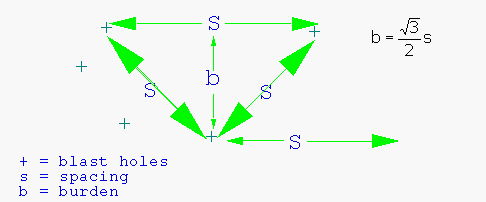
Diagram 4 - Length of Triangle Side
Text size
Enter the size, in plotter units, of the drillhole annotations. The finished blast can then be plotted. The size of the text on the screen is in relation to the map scale.
Map scale
Enter the map scale. The map scale and the size of the text will determine the size of the text on the screen. For example, if the text size is set to 0.30 and the map scale to 1:100, text will appear on the screen the same size as an object that is 30 units tall.
Text rotation
Enter the angle of rotation of the text block. For example, 0° = horizontal (as normal text), 90° = vertical.
Accuracy
Enter the tolerance factor for generating registered outlines.
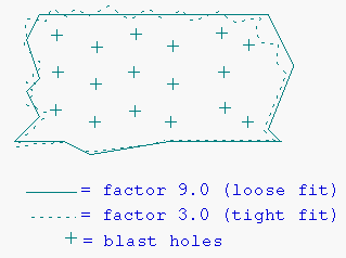
Diagram 5 - Tolerance Factor
Hole name prefix
Enter an optional 5 alphanumeric character prefix. This prefix will be used to name the holes.
Density
Enter the density. The density is used to calculate tonnage in the Tonnage option under Explosive Analysis.
Symbol radius
Enter, in metres, the radius of the symbols.
Offset compared holes
Select this check box to offset compared holes by a tolerance. The tolerance is specified through the Comparison option.
Colours
Select colours for the following:
- designed outline
- registered outline
- Tie in
- layout holes
- survey holes
- single holes
- compared holes
Select OK.
The design database (<proj><deposit>.dgd) is opened and relevant layers (<bench number>_<blast number>_*) loaded.

