Highwall Road Parameters
The Highwall Road Parameters panels support road design specifically for a highwall mine.
Example
The following is an representation of a switchback road for a single strip.

Instructions
Follow these instructions to design a road specifically for a highwall mine.
- Before you begin, ensure that the layer containing a strip object is loaded. It is also recommended that you load a string indicating the start position. This will simplify road construction with multiple strips.
- To access the Road Parameters panel, click Open Pit > Ramps > Design Pit/Dump.
- Select Highwall from the top left drop-down list, and for Spec name select a specification file from the drop-down list.
- In the General tab, for Road, select whether the road goes up or down the wall in the Road goes radio option.
- In the Miscellaneous tab, for Projection, populate the horizon list by loading an appropriate specification file. (.gdc_glob, .rsp, .bb_spec, and .hw_spec files are supported.)
- To save a road layout for later reuse, in Saving, select Retain road construction. Click OK.
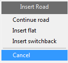
- In the 'Create Pit' context menu, select Insert Road.
-
Select the string representing the top or bottom surface line on the strip object, and click Register.

-
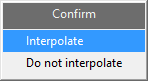
Confirm to interpolate the line.
-
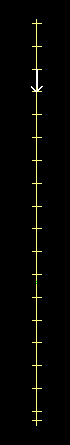
Then select the point where the surface line intersects the road start line.
-
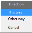
Depending on the direction of the arrow that appears, select This way or Other way.
-
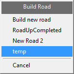
Select Build new road from the context menu. Select or enter a name for the road and click OK.

-
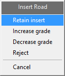
If the road is correct, click Retain Insert. If required, increase or decrease the grade.
-
To continue building the road, select from the following options. For information on these options, see
Continue Road,
Insert Flat, and
Insert Switchback
respectively.

- After completing an Insert Road option, retain the insert when required.
-
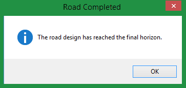
Continue selecting these options to build the road until the final horizon is reached. Click OK to confirm completion of the road.
- A road design similar to that shown in the Example section above should appear.
Automated Road Construction
Automated road construction is useful when working with multiple strips. To automate the road construction process, you need a saved road layout. This is made once you complete construction of a road or halt construction midway due to an error, AND if Retain road construction is selected in Road Parameters > Highwall > Saving.
- Once you have a saved road layout, clear Retain road construction in Road Parameters > Highwall > Saving.
- Select the Insert Road option in the Create Pit context menu.
- Select the saved road layout.
-
The road is automatically constructed according to the saved road layout.
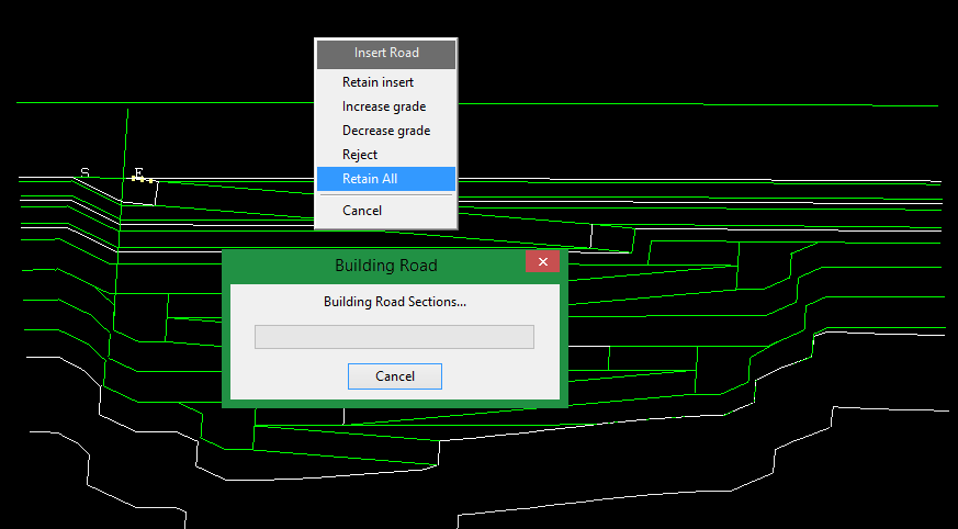
- Click Retain All to automatically build the road without stopping until completion.
- Click Retain Insert to build the complete road with a pause at each section.
Panel Descriptions
- General
- Miscellaneous
- Strip
- Saving
The following sections describe the fields in the Road Parameters - Highwall panels.

Road Parameters - Highwall panel
Spec name
Refers to the set of parameters that are currently being used. The drop-down list contains all of the parameter definitions found within your Ramps Parameters file (<proj>.pit_spec2). Your Ramps Parameters file should be located within your current working directory.
Click Save As if you want to create a new set of parameters or save any changes. To delete an existing set of parameters, click Delete.
The remainder of this panel consists of the following sections:
General
Use the General panel to set up standard road parameters.
Road
Road goes
Specify whether the road is to go up or down from the selected string.
Width
Enter the true width of the road.
Grade
Enter the grade of the road as a percentage, a ratio or in decimal degrees by selecting the appropriate angle format button and entering a value. The format of <negative value>:<value> must be used when entering negative ratios, for example '-1:7'.
For example: To enter a value of 50%, select the % button and enter '50'. Select a different angle format button if you want to convert a value.
The direction of the grade is determined by the Up the wall and Down the wall options.
Grade
Apply grade to section of road
These options determine the side on which the road is graded. For a straight road this has no effect. For a road that turns in any direction, each side of the road will have a different grade. This is because both sides of the road have the same change in elevation, but go through different distances to achieve it. These options select where the grade will be applied.
-
Shortest option will apply the specified grade for whichever side is shortest.
-
Centre is the midway between the Highwall and the Highwall opposite.
-
Highwall refers to the side of the road on the original wall.
-
Highwall opposite refers to the side opposite the highwall side.
Note Because the Highwall grading is applied directly to the wall, it will always be accurate. Any other gradings use an iterative algorithm, and will be accurate to a nominated tolerance (0.1% by default- see Advanced options).
Grade increment (for adjustment)
The grade increment is used when inserting a road and subsequently adjusting the grade.
Select an angle format from percentage, ratio, or decimal degree options, and enter a value. The format of <negative value>:<value> must be used when entering negative ratios, for example ' -1:7 '.
For example: To enter a value of 50%, select the % button and enter '50'. Select a different angle format button if you want to convert a value.
Bench Access
Allow bench access
Check the Inside/slot cut left and Outside/slot cut right check boxes to allow access to the benches on either side of the road. These check boxes must be ticked before the road is created. If a road is inserted and a projection to the bench has been done, then any subsequent berm will be created according to what was ticked here.
To change the access to the bench, repeat insertion of the road.
Fractional access ratio
Specify what proportion of the bench is accessible. A bench access value of '1.0' will allow full access to the bench with a berm width as defined above. A bench access value of '0.0' is equivalent to no bench access. You can also have any fraction in between.
To accommodate bench access the road width is changed. If the amount of access varies from one bench to the next, you may need to modify the road width to compensate.
Maintain full road width
Select this check box if you want to maintain the full road width between projections.
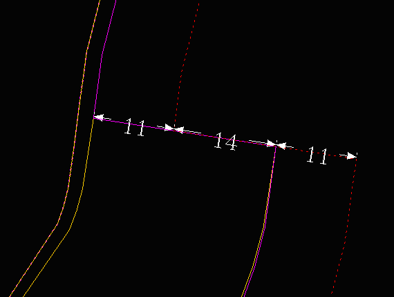
For example, if you use a road width of '25' and a berm width of '19', and both Allow bench access check boxes are ticked with fractional access ratios of '1.0' applied, then the resulting road will be similar to the following:
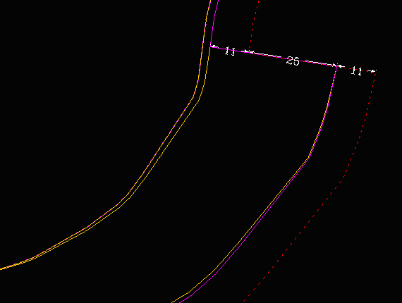
If you used the same parameters as mentioned above and ticked the Maintain full road width check box, then the resulting road would look similar to the following:
Adjust road
Lock start to edge to existing road edge
The documentation for this field is currently being worked on.
Apply proximity filter to points near road edge
This option is used to remove points close to the edge of the road. These tend to be a major source of problems in placing the road.
Tolerance for centre and inside grades
This option refers to the accuracy with which these grades can be obtained via the iterative method that is used.
Miscellaneous
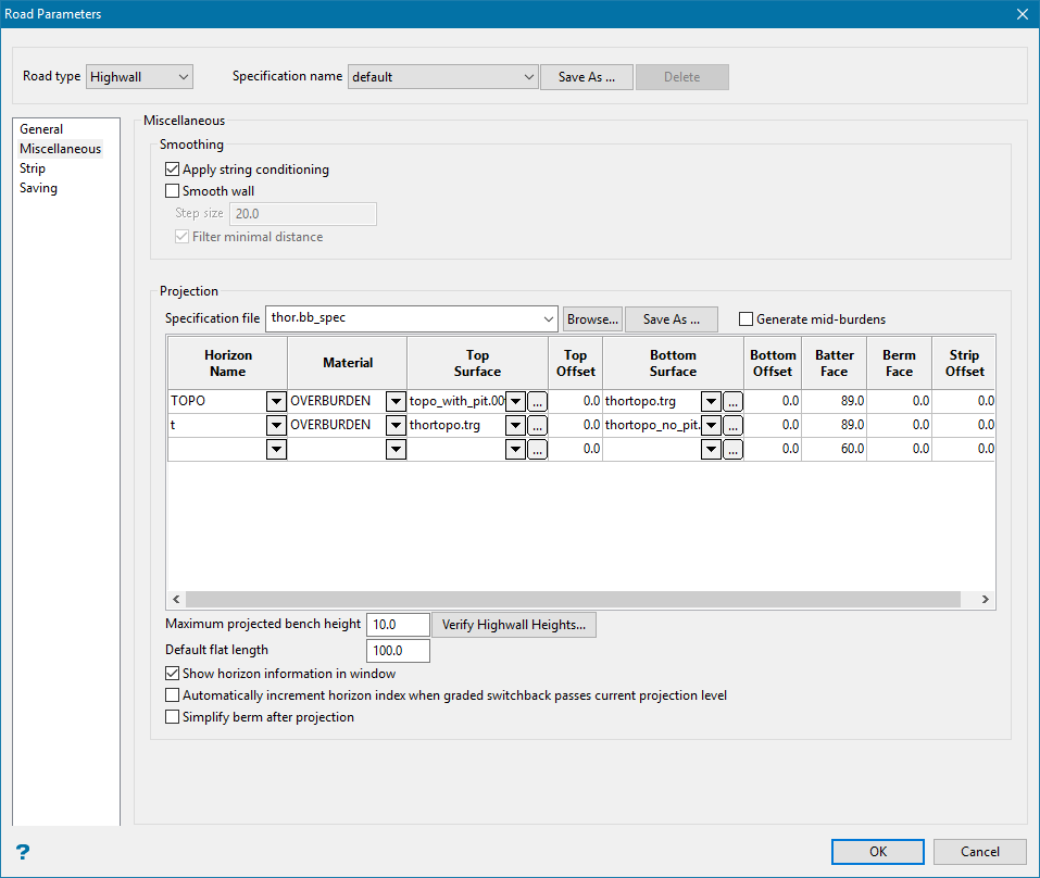
Road Parameters - Highwall - Miscellaneous panel
Smoothing
Apply string conditioning
String conditioning carries out checks on points in toe or crest strings. The String Conditioning panel will appear once you complete the Miscellaneous panel and click OK, letting you specify the string checks to be carried out.
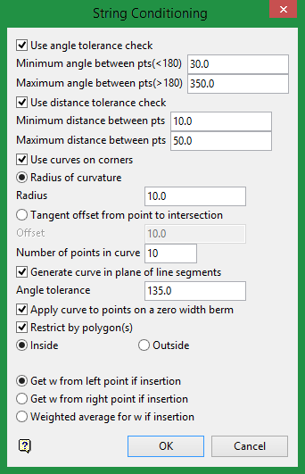
Refer to the Condition string option for more information on this panel.
Smooth wall
Select this check box to apply a spline style to the polygon. This type of smoothing produces good results for rounded pits. If this check box is checked, then you will need to specify a step size. The step size value will control the distance between each point.
Check the Filter minimal distance check box to ensure that no extra points fall between 0 and the specified step size value. We recommend that you check the Filter minimal distance check box to ensure that there is more consistency between the points and to avoid sharp edges.
Projection
This section contains the horizon list, ordered from top to bottom. So if the road direction goes up, then road construction begins at the highest index horizon and continues the lowest. The horizon list is separate from the road layout and It is possible to apply a road layout to a different horizon configuration. Additional horizons may be inserted during the road construction process, and the current index will adjust to reflect the new index order.
Specification File
The specification file field can be populated by .gdc_glob, .rsp or .bb_spec files. This field also allows the loading of hw_spec files which contain the contents of the horizon list.
Generate mid-burdens
Selecting this box automatically populates the projection table with rows containing midburden values.
Horizon Name
Enter or select from the drop-down list an identifying name for the horizon.
Material
This column lists the type of material associated with each horizon. Options are Coal, Midburden, and Overburden. Values are automatically populated from contents of the selected specification file. Alternatively, they may be manually entered or selected from the drop-down list.
Top Surface
This column lists the grids or triangulations defining the top surface for each horizon.
Top Offset
An distance value which adjusts the height of the top surface. A typical value is 60m.
Bottom Surface
This column lists the grids or triangulations defining the bottom surface for each horizon.
Bottom Offset
An distance value which adjusts the height of the bottom surface. A typical value is 60m.
Batter Face
The angle at which the projection of the wall is made at.
Berm Face
The length at which the road is bermed. This takes into account the bench access value specified in the general settings.
Strip Offset
The length at which the road is bermed. This function acts like a full berm of the string, and the road points are moved further along the open string.
Verify Highwall Heights
This option checks whether the height difference between horizons at a given object's location is larger than the specified maximum bench height.
If the height exceeds the maximum bench height, then a grid at the maximum bench height is created and inserted into the table. Only grids are supported when using this functionality, and any triangulations will cause this operation to fail.
Default Flat Length
Enter the length of the flat section created using the Insert flat option.
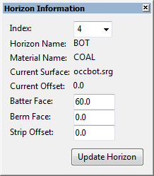
Show horizon information in window
This option displays the Horizon Information panel when the Road Parameters window is closed. The Horizon Information panel displays the horizon that the user is limited to. In addition, it allows configuration of the current horizon, and the batter, berm, or strip offset values. Changes to these values will be replicated in the specification file and can be seen in the Road Parameters horizon list.
Automatically increment horizon index when grade switchback passes current projection level
Automatically increments the current horizon index without notifying the user. If the option is disabled, a prompt will be shown if the end of the graded switchback passes through the current limiting surface. The user has the option to increment the horizon index or leave it as it currently is.
Simplify berm after projection
Sometimes at the beginning or ending of a ramp waves can be created in the pit design. Use this option to try fixing this effect.
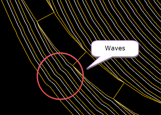
Figure 1: Waves created in pit design.
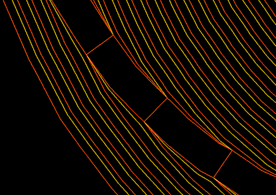
Figure 2: Pit design after correction has been applied.
Strip
Use this panel to list the road objects from which the road is built.
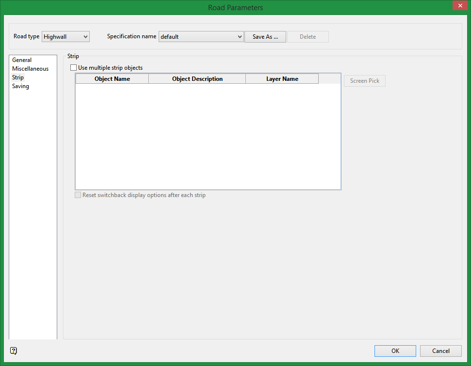
Road Panel - Highwall - Strip panel
Use multiple strip objects
This option allows the user to select multiple open strings to insert roads into. Each object's information (name, description, and the layer which it resides in) is shown to the user in a table.
The selected objects need to be located in their own layer due to design requirements. Options under the Saving tab use the layer name as a base for further layer and triangulation construction.
Reset switchback display options after each strip
Select this option to display the Graded or Flat Switchback Parameter panel options even if the user has enabled Always use these settings on the one of these panels (see Graded and Flat Switchback Parameters ). Leaving this option disabled will cause the previous values of the switchback panels to be used instead of prompting the user for each new strip.
Saving
Use this panel to how road parameters are saved.
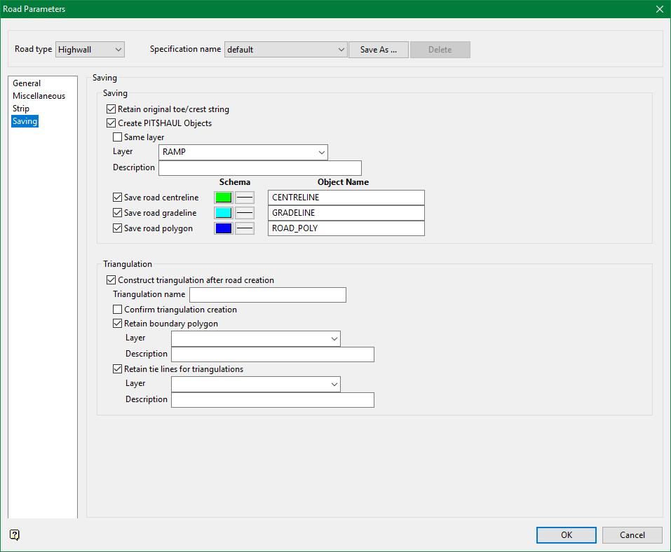
Saving
Retain original toe/crest string
Select this check box if you want to retain the original string into which the road is inserted. If this check box is not ticked, then the original string will be replaced by the road and string combination.
Create PIT$HAUL Objects
Select this check box to create ramp objects like centreline, gradeline, and road polygon. Centreline is drawn mid-point between the two edges of the road.
Select the Same layer option to save the resulting objects in the same layer that you are working on. Unchecking this will give you the option to enter a new layer name and its description. Enter the Layer where you want the resulting objects to be saved to.
There are three different options for creating centreline, gradeline, and road polygon. Select these options to save the desired objects. You can use the default names provided or supply your own names for naming these objects. You can also change the colour and line style to distinguish the objects from one another.
Diagram 1 - Centreline, Gradeline, and Road polygon
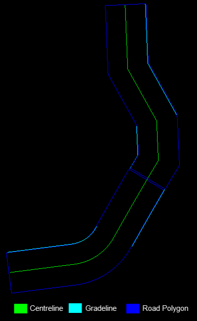
Note: The centrelines for each ramp are connected to one another other as a single object while the gradelines and road polygons are separated.
Triangulation
Construct triangulation after road creation
This feature automatically takes the road that was created and creates a triangulation to act as a template for the construction of additional roads.
Retain boundary polygon
Allows the user to keep the boundary polygon that was used to help construct the highwall template triangulation.
Retain tie lines for triangulations
Allows the user to keep the tie lines that were used to help construct the highwall template triangulation.
When the multiple strip functionality is not enabled, the user must enter a layer and triangulation name for each of the options that they have selected. When the multiple strip functionality is enabled, the triangulation name is the same as the strip layer name, the road layer is the layer name with _road appended to it, the boundary layer is the layer name with _boundary appended to it, and the tie line layer is the layer name with _tieline appended to it.
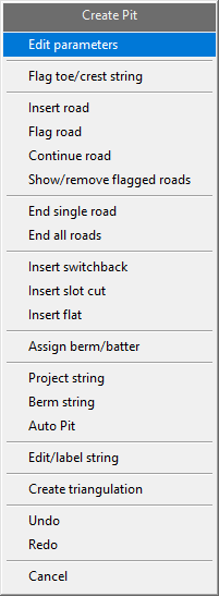
Create Pit menu
Subsequent selection of this option will produce the Create Pit dialog box. This dialog box contains all of the options that are related to the actual creation and modification of pits and ramps, including an option to edit the current road parameters.
This option returns you to the main panel.
Use the Flag Toe/Crest string option to apply standard Vulcan naming conventions to pit or dump strings. This option requires that you identify individual pit or dump strings as a 'toe' or 'crest'.
Select the lowest string in the pit or dump design. Identify this string as a 'toe' or a 'crest'.
The next string can then be selected. Again, you will be asked whether this string is a crest or toe. Cancel when finished.
Naming conventions are then assigned to each string as follows:
PRU<value> (for crests)
BRU<value> (for toes)
These naming conventions are required by other options in the Open Cut Design, Ramps and Phase Design submenus.
Note: Once a string has been defined as a crest or toe string, it will inherit the graphical attributes (colour and line type) set through the Graphics Toe/Crest/Road option.
The most common application of this option is when the starting string of a pit or dump has been digitised manually, or created through the Register option (under the Design > Object Edit submenu), which does not apply the open pit naming conventions. You don't need to use this option when the pit or dump has been entirely designed using the Design Pit/Dump option (under the Open Pit > Ramps submenu).
This option also sets the group and feature codes of the object. Crests are allocated to the PIT$CREST group with the PIT$PROJ feature. Toe strings are allocated to the PIT$TOE group with the PIT$BERM feature code.
Use the Insert road option to insert a road at a new location. Before you begin, ensure you have correctly set the direction of the road on the General tab of Road Parameters > Simple/Advanced/Highwall.
-
Select the string into which the road is inserted. The string can be open or closed but must follow the standard pit design string conventions. The string is highlighted and you are asked to select a starting point.
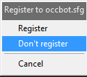
- Register, Don't Register
- The Register function matches points in the selected string with the starting grid. For example, if the road goes up, the starting grid is the bottom surface, and vice versa for a downwards road. Registering a string with a surface results in a more realistic model of the strip and road.
-
A direction is highlighted. Select either the indicated direction, or the opposite direction. The default direction is clockwise the first time selected, otherwise it is the last selected direction. For a string formed from a previous road inserted, the direction is determined by the previous road.
-
You are asked to build a new road or insert a saved road layout.
-
A highlighted road displays and you are asked whether to retain or reject the insert, or modify the grade. If inserting a saved road layout, the Retain All is also available.
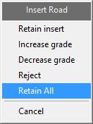
- Retain insert
- This saves the constructed road to the selected road layout. A selection of road building functions then appears.
For information on these options, see Continue Road, Insert Flat, and Insert Switchback respectively.
- Increase grade, Decrease grade
- Choosing Increase grade or Decrease grade allows you to modify the road grade by 0.5%. This is useful if you need the road to end at an exact location or to get around tight inside corners. Also highlighted is a thick dashed line that indicates where the grading is applied.
- Reject
- This cancels the current road construction step, and returns to the previous step in the road layout.
- Retain All
- This option automates the road construction process. Once Retain All is selected, the saved road layout is used to create a road.
The road creation process pauses before completion only for input on parameters, such as flat or graded switchback parameters, errors, road completion, or if the last horizon has been reached.
Note: Using the Increase grade option will result in a steeper ramp, while the Decrease grade option will result in shallower grades for both positive and negative grade values.
The road lengths and grades are displayed in the Report Window.
Upon finishing you will be returned to the Create Pit dialog box.
Note: After completion of the road construction process, Road Parameter values are reset to null. Return to the Road Parameter panels to set up road construction parameters.
Use the Flag road option is used in the special case where you want to insert a road into a pit string that has a road defined, but was not generated using the Ramps module. For example, this could be used to add roads to strings imported from outside Vulcan.
Select the string, road start point and direction as you would for Insert road. This option then changes the point names on the string, so that you can use the Continue road option to place the road correctly.
Use the Continue road option to continue an existing road(s).
Once selected, you will be required to select the string from which to start the continuation. Information regarding the location of the road, is contained in the point names of the string. It is therefore important not to interfere with the point names of any of the strings.
Tip: We recommend that you flag the polygon before using the Continue road option. To ensure that the projections are accurate, we also recommend that you check that the road widths are correct.
Use the Show/Remove flagged roads option to identify where the roads are flagged in the polygon.
End single road
Use the End single road option to clear the point name road flag in a specific area of the polygon. Doing so stop a road on an existing string from developing any further.
Once the option has been selected, you will be prompted to select the point on the string at which you want to stop. This option will then remove the point names for that part of the string, so it is not taken into account for further projections.
Use the End all roads option to clear all of the point name road flags in a nominated polygon or line. Doing so stop all roads on an existing string from developing any further.
Once the option has been selected, you will be prompted to select the point on the string at which you want to stop. This option will then remove the point names for that part of the string, so it is not taken into account for further projections.
Use the Insert switchback option to insert a switchback (a flat switchback or a graded switchback).
Once this option has been selected, you will be prompted to nominate a string followed by the starting point for the switchback. The starting point refers to the inner most point of the string, that is, the start of the road.
The following panel is then displayed.
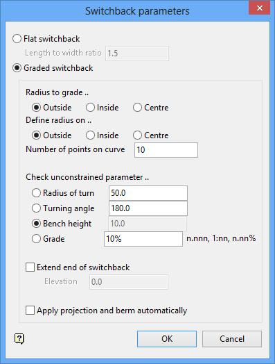
Switchback parameters panel
Flat switchback
Select this option to insert a flat switchback. You will need to specify the length to width ratio that will be applied to the distance of the last projected road and the wall. If the ratio is set to '1.0', then the width of the road and the distance to the wall will be the same.
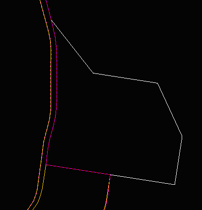
Diagram 1 - A Flat Switchback
Graded switchback
Select this option to insert a graded switchback.
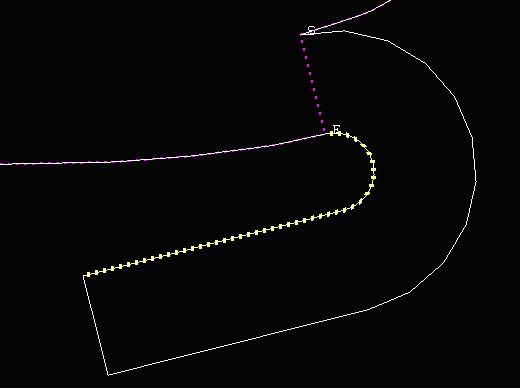
Diagram 2 - A Graded Switchback
The following options are only available when inserting a graded switchback.
Radius to grade
Nominate the radius to which to apply a grade (outside, inside, centre).
Define radius on
Specify where the defined radius is to be applied (usually the inside).
Number of points on curve
Enter the number of points to draw on the curve. The more points, the smoother the curve.
Check unconstrained parameter
A switchback curve is constrained by the relationship:
H = A R tan (G)
where H = bench height; A = turning angle; R = radius of turn; G = ramp grade.
Therefore when designing the switchback curve, you can specify three of the above parameters and the software calculates the fourth. You select which parameter you want the software to calculate. The parameter value for the selected field is shadowed.
If the radius is selected as the unconstrained parameter, then you cannot choose where to apply the radius. If the grade is selected as the unconstrained parameter, then you cannot select where to apply the grade.
Extend end of switchback
Select this check box to extend the switchback to a nominated elevation. When the switchback is created the parameters are displayed in the Report Window.
Select OK.
Once created, you must use the Project string option and project the string to a level equal to the highest point on the switchback (that is, the end point). Use the opposite if you are building from the surface down and not bottom up.
You will then need to remove the extra points in the corners of the projected crest line followed by berming the crest string (via using the Berm string option).
Snap the berm to the end of the switchback and continue the road (using the Continue road option).
Graded and Flat Switchback Parameters
The Graded Switchback parameters and Flat Switchback parameters panels appear when using the Insert Road option in the Create Pits context menu with a saved road layout which includes one or more switchbacks. When the road building process reaches a saved switchback in the road layout, either of these panels appear.
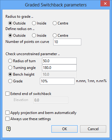
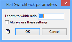
Graded Switchback parameters and Flat Switchback parameters panels
These panels are cutdown versions of the Switchback Parameters panel with the additional option of Always use these settings. This setting, which operates separately for the Graded or Flat Switchback parameters panels, supports the automation of the road building process. However, it can be overridden by selecting Reset switchback display options after each strip in the Design Pit Dump > Road Parameters > Highwall > Strip tab.
Use the Insert slot cut option to insert a slot cut road into a polygon.
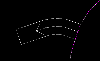
Diagram 1 - Slot cut road
If needed, this option can also be used to create a graded switchback.

Once this option has been selected, the following panel displays.
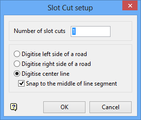
Slot Cut setup panel
Number of slot cuts
Enter the number of slot cuts to insert into the current pit design (the default value is '1').
Digitize left side of a road
Select this option to have the user defined line on the left side of a road (if you are designing a pit upwards).
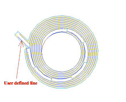
Diagram 2 - User defined line on the left
Digitize right side of a road
Select this option to have the user defined line on the right side of a road (if you are designing a pit upwards).
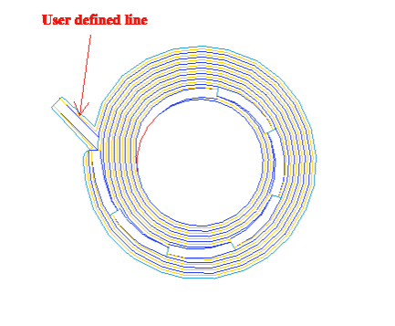
Diagram 3 - User defined line on the right
Digitize centre line
Select this option to have the user defined line at the centre of the haul road.
Snap to the middle of line segment
Select this check box to snap the centreline to the middle of a line segment (distance between two points).
Select OK.
Select the string to insert the slot cut road into. You will need to confirm your selection.
Select a line segment to start centreline road 1. You will then need to indicate the next point. Confirm that all points have been indicated by selecting Accept line. Select Retain Insert to confirm the changes.
The Insert flat option is similar to the Insert road option, however, instead of a graded road, it generates a flat section of road. The length of this section is determined by the Default flat length parameter in the Road Parameters panel.
The Assign Berm/Batter option to apply batter angles and berm widths to a pit or dump outline before projecting it. The Assign Berm/Batter option is identical to the Assign Berm/Batter values option (under the Open Pit > Open Cut Design and Open Pit > Ramps submenus).
The Project string option is similar to the Project string option (under the Open Pit > Open Cut Design submenu). In addition it knows about the road insertion and properly designs the projected string to be suitable for continuing road designs.
The batter angle from the Road parameters panel is not automatically put into this panel. To match the projection with an inserted road, you must, however, enter the same batter angle as defined in the Road parameters panel.
Note: The Design Pit/Dump option applies the above batter angle to entire strings. To apply different batter angles to different line segments, use the Assign Berm/Batter option.
The project to level field must be set with the desired bench height and with the 'M' prefix (the bench height from the Road parameters panel is not automatically put into the Bench Projection panel). When generating a road down the pit, the project to level value must be negative. The nominal bench height field on this panel has no affect on this option.
The Berm string option is similar to the Berm string option (under the Open Pit > Open Cut Design submenu). In addition it knows about road insertions and correctly designs the bermed string for further road development. It also adjusts the bermed string as to whether or not bench access is required.
The berm width from the Road parameters panel is not automatically put into this panel. To perform the correct berm, you must enter a default berm width of '0.0' and disable the Override berm widths with default check box. The road insertion operations set the berm widths on the W tags of the string to the default value, determined in the Road parameters option, unless there is already a berm width specified.
Note: The Design Pit/Dump option applies the above berm width to entire strings. To apply different berm widths to different line segments, use the Assign Berm/Batter option.
Use the Auto Pit option to generate automatically a pit or dump from a selected outline, using constant bench heights and widths. The pit/dump can be limited to a nominated depth or limited by approximate volume. You can also interactively generate double or triple benches and change the projection parameters, such as batter angle, berm width and bench height.
The Auto Pit option is identical to the Auto Pit option (under the Open Pit > Open Cut Design).
Once selected, the Editing dialog box displays. This dialog box contains the following options.
Replace string
Dynamic replace string
Insert point
Insert point at intersection
Move point
Delete point
Delete string
Object Z Value
Point Z Edit
Grade
Relimit by Distance
Point Interpolate
Close Polygon
Apply Curve
Condition string
Smooth wall
Label Point Name
Label Point Z Value
Label Point W
Point Sequence
Distance
Label Remove
Note The contents of the displayed dialog box are controlled by the settings defined under the Ramps section of the Tools > Preferences option.
Replace string
The Replace string option to replace a section of an existing string. The Replace string option is identical to the Design > Point Insert Replace String option.
Dynamic replace string
The Dynamic replace string option to dynamically replace a nominated section of an existing design object with a Bézier spline curve. The Dynamic replace string option is identical to the Design > Point Insert > Dynamic Replace String option.
Insert point
The Insert point option to insert extra points into a particular line segment of a string. The Insert point option is identical to the Design > Point Insert > Insert option.
Insert point at intersection
The Insert point at Intersection option to insert an extra point into a line segment where the segment is intersected by another line. The Insert point at intersection option is identical to the Design > Point Insert > Insert At Intersection option.
Move point
The Move point option to move a point to a new position. The Move point option is identical to the Design > Point Edit > Move option.
Delete point
The Delete point option to remove individual points from an object. The Delete point option is identical to the Design > Point Edit > Delete option.
Delete string
The Delete string option to delete a section from a string of points. The Delete string option is identical to the Design > Point Edit > Cut option.
Grade
The Grade option to apply a gradient to a nominated string or part of a string. The Grade option is identical to the Design > Object Edit > Grade option.
Object Z Value
The Object Z Value option to apply a nominated Z value to an object. The Object Z Value option is identical to the Design > Object Edit > Z Value option.
Point Z Edit
Point Z Edit option to change the Z value of a point. The Point Z Edit option is identical to the ![]() Design > Point Edit > Z Edit option.
Design > Point Edit > Z Edit option.
Relimit by Distance
The Relimit by Distance option to reset the length of an existing line. The Relimit by Distance option is identical to the Design > Relimit > Distance option.
Point Interpolate
The Point Interpolate option to insert points into a line segment along a grade. The points can be either at a nominated distance apart or be equally spaced along the line segment.
The Point Interpolate option is identical to the Design > Point Insert > Interpolate option.
Close Polygon
The Close Polygon option to close an object by automatically connecting the first and last points in a string. The Close Polygon option is identical to the Design > Attribute Edit >Close Polygon option.
Apply Curve
The Apply Curve option to apply a curve of a nominated radius or tangent to strings. The Apply Curve option is identical to the Design > Point Insert > Apply Curve option.
Condition string
The Condition string option to perform checks on the nominated toe or crest strings to determine if points must be added or deleted to satisfy certain conditions. The Condition string option is identical to the Open Pit > Open Cut Design > Condition string and Open Pit > Ramps > Condition string options.
Smooth wall
The Smooth wall option to applying smoothing to polygons prior to starting the pit design process. We recommend that you digitise the polygon and flag the roads (to update the point names) before using the Smooth wall option.
Choosing not to use this option on the first polygon and using the Smooth wall check box (on the Road Parameters panel) instead could result in the following.
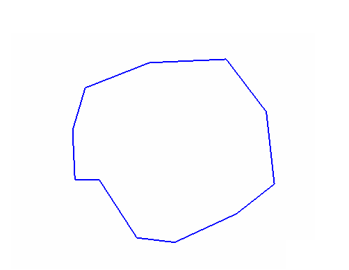
Diagram 1 - The original polygon
If you don't apply the Smooth wall option before applying the Continue road option, then the following will be produced.
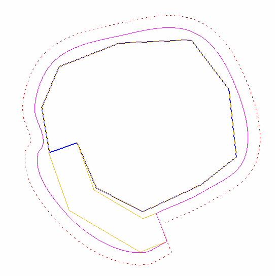
Diagram 2 - The resulting pit
The correct procedure is to apply the Smooth wall option first followed by the Continue road option. Doing so will result rounded pits (as shown below).

Diagram 3 - The original polygon
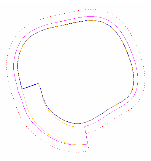
Diagram 4 - The resulting pit
Label Point Name
The Label Point Name option to label points with their names. The labels displays in a fixed (non-transformable) font. Text in a non-transformable font remains the same on the screen regardless of the current zoom and will always appear 'face on' (horizontal), regardless of screen orientation.
The resulting labels can contain up to 6 decimal places. The default numbers of decimal places is derived from the Miscellaneous section of the Tools > Preferences option.
Label Point Z Value
The Label Point Z Value option to label points with their Z value. The resulting labels can contain up to 6 decimal places. The default numbers of decimal places is derived from the Miscellaneous section of the Tools > Preferences option.
Label Point W
The Label Point W Tag option to label points with their W values. The resulting labels can contain up to 6 decimal places. The default numbers of decimal places is derived from the Miscellaneous section of the Tools > Preferences option.
Point Sequence
The Point Sequence option to label the points with their sequence number, that is, the order of digitising. Knowing the order of digitising or the location of the first and last points, may be necessary when, for example, appending objects.
Once selected, you will need to specify whether to label all points in the chosen object or just the first and last points.
The Multiple Selection box is then displayed. From this box, choose your method of selecting the objects and select the objects.
Distance
The Distance option to measure the straight line distance between nominated points.
Once selected, you will be prompted to indicate two points. Any position on the screen can be indicated, that is, you don't need to use an existing point. You can, however, use ![]() Snap to Objects or
Snap to Objects or ![]() Snap to Points mode to snap onto a specific point.
Snap to Points mode to snap onto a specific point.
The Report Window displays the Total length, Plan length (which will differ from the total length if the view has been rotated), bearing and gradient between the two points. Continue indicating points. After each point has been indicated, the relevant information displays through the Report Window.
Label Remove
The Label Remove option to remove the labels that have been displayed.
Once selected, the Create Triangulation dialog box displays. This dialog box contains the following options.
Triangle Surface Create
The Triangle Surface Create option to create a triangle model by triangulating data points. The Triangle Surface Create option is identical to the Model > Triangle Surface > Create option.
Triangle Solid Shells
The Triangle Solid Shells option to clip a triangulation between a series of successive planes and produce new triangulations. The resulting triangulations, which are also known as 'shell triangulations', can be created with fixed or varying widths. The W tag of a nominated string can also be used to control to the width of the resulting triangulations.
The Triangle Solid Shells option is identical to the Model > Triangle Solid > Shells option.
Triangle Utility Boolean
The Triangle Utility Boolean option allows two loaded triangulations to be intersected precisely. You can then choose which of the pieces (referred to as "splits") to include in the new model.
The Triangle Utility Boolean option is identical to the Model > Triangle Utility > Boolean option.
Pit Topography
The Pit Topography option to generate an updated pit topography, pushback solid and topography intersection line for a previous topographic surface against a surface of a new pit design.
The Pit Topography option is identical to the Pit Topography option (under the Open Pit > Open Cut Design submenu).
Note: This is available only if Highwall has been loaded in Road Parameters (via Edit Parameters in Create Pit context menu.
Select Highwall Options in the Create Pit context menu. If the Road Parameters > Highwall panel has been loaded, the Highwall Options context menu appears.
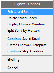
Highwall Options context menu
Edit Saved Roads
Allows the user to edit the name and sections of the road that were saved during the construction of a road. To edit a road, select a road from the pop-up dialog. This dialog only appears if there is more than one saved road. A single saved road is automatically selected. The Edit Saved Road panel appears with information on the road name and sections.
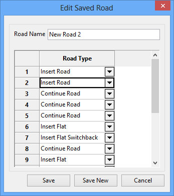
Edit Saved Road panel
It is recommended that you check that the saved road types match the completed road. Extra road sections should be deleted, by right-clicking on the unnecessary road type and selecting Delete.
Create Pit context menu commands such as Undo are also saved in this list and should be deleted. If deleting Undo, also delete the previous command associated with the Undo.
If inserting a Road Type, it is recommended that you select one from the drop-down list. Manually entering a string that differs from the ones provided will cause the road building functionality to fail.
Clicking Save New saves a new road type. If a road type already exists with the same name, a second version is created and listed in numerical order.
Delete Saved Roads
Brings up a pop-up window that shows the user all of the currently saved roads available. Selecting an option will delete the road. If only one road was saved, it will be automatically deleted without needing to be selected.
Display Horizon Window
Re-displays the horizon information window if it was closed by the user.
Split Solid by Horizon
Allows the user to perform operations on triangulations that is similar to the Model > Triangle Utility > Merge option with the Solid above surface and Solid below surface options selected.
Solids tab
Select the solid triangulations that you want to split, either by using the list select tool, screen picking the triangulations, or by browsing for the required solids.
Surfaces tab
Select the surfaces that you want to use to split the solid. The same selection methods are available.
The order of the surface triangulations is important, and must be in the order from the lowest surface to the highest. The glob file provides that ordering. For other input methods, you can use the Move Up or Move Down to re-order the surfaces.
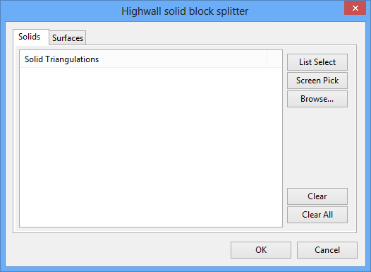
Highwall solid block splitter panel
Continue Saved Road
Allows the user to resume any saved road that was interrupted during construction. This will continue on from the last successful road piece that was created.
Create Highwall Template
Allows the user to recreate the triangulation that the current finished road layout would create. This allows the user to fix any created triangulation by modifying any broken pieces of road layout, or inconsistent tie lines before selecting the Create Highwall Template option. Running this option without any saved road will not result in a triangulation.
Continue Strip Creation
Allows the user to continue with the multiple strip functionality after pausing to create a triangulation. The next strip in order will proceed to have its road constructed..
Shelling
Opens up the Model > Triangle Solid > Shells menu.
The Undo option to undo any recently made changes.
Use the Redo option to reinstate the changes that were cancelled through the Undo option.
The contents of the displayed dialog box are controlled by the settings defined under the Ramps section of the Tools > Preferences option.

