Laser Offsets
Use this option to create offset lines from a centreline at certain spacing distances to the walls of the drive.
These offsets are displayed while plotting.
Instructions
On the Survey menu, point to UG Survey, and then click Laser Offsets to display the panel.
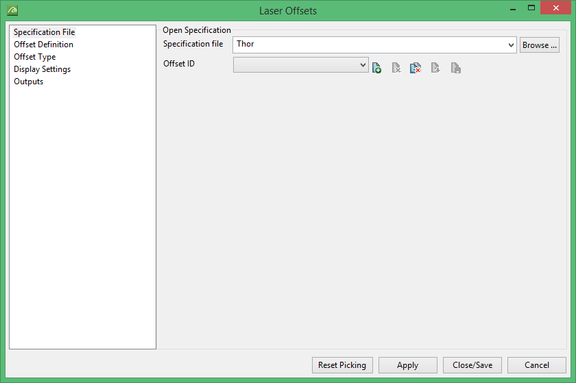
Open Specification
Specification file
Use the drop-down list to select the specification file if it is in the current working directory, or browse for it in another location by clicking the Browse button. You may also create a new file by typing the name of the new file in the textbox.
Offset ID
Use the drop-down list to select the ID file, or create a new one by clicking the New icon.
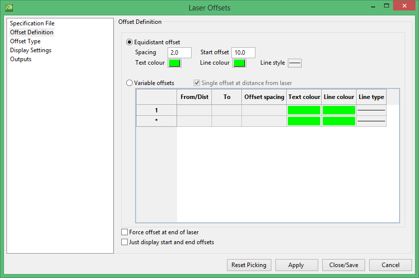
Offset Definition
Equidistant Offset
Spacing
Enter the spacing for the grid lines.
Start Offset
Enter the distance from initial reference point at which the first grid line will begin.
Enter graphic preferences for Text colour, Line colour and Line style
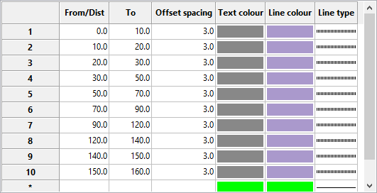
Variable offsets
This option allows the user to enter variable distances between steps rather than uniform distances. Enter the starting point of the first step in the From/Dist column and the ending point in the To column. Offset spacing is entered in the third column. Note that the offset spacing must be a number smaller than the difference between the number in the To column and the number in the number in the From/Dist column. For example, the difference between the starting and ending number in row 1 in the table below is 10, so the offset cannot be greater than 10.
Single offset at distance from laser
Selecting this option will allowing you to enter data into the From/Dist column in the table.
Force offset at end of laser
If this option is selected then the distance from the last step to the end of the traverse will be displayed even if it is only a partial distance. For example, if all the steps in the grid are set at 10m offsets and there is only 8.75m left in the drift, then the display will show 8.75m as the last offset distance.
Just display start and end offsets
If this option is selected then only the beginning and ending of the traverse will be displayed on the screen.
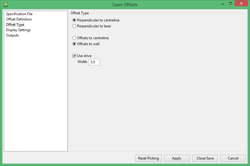
Offset Type
Choose whether you want the offset to be based off the Perpendicular to centreline or Perpendicular to laser, and Offsets to centreline or Offsets to wall.
Use drive
Select this for an offset centreline (for example, in a 7m wide heading the centreline to left wall might be 2.5m, but centreline to right wall might be 4.5m.)
When offset lines from a custom drive centreline are created one offset will fall short of the design wall.

Display Settings
Display laser points
Select this option if you want the laser points to show on the screen. If so, then select the colour of the points.
Display laser symbol
Choosing this option and clicking the  will prompt you to select a symbol from the library.
Offset Table
Post table in graphics
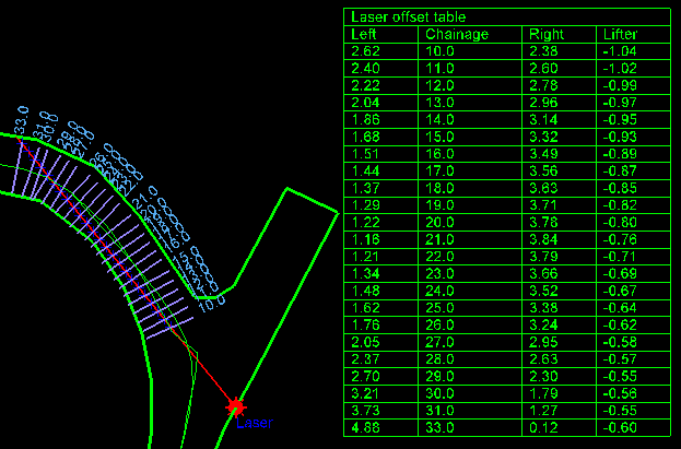
Select this option is you wish to display a table on the screen similar to the example below.
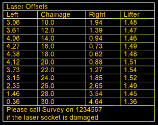
Title, text colour, line colour, line style, line style border, size of text on plot and cm at drafting scale are all adjustable according to user preferences.

Outputs
CSV file name
Enter the name of the CSV file or click  to locate an existing file.
Layer name
Enter the name for the layer in the Design Database where the data will go.
Automatically overwrite existing CSV file
If this is selected files with the same name will be overwritten.
Automatically overwrite existing layer
If this is selected files with the same name will be overwritten.
Decimals
Left/right
The distance left and right of the centreline.
Lifters
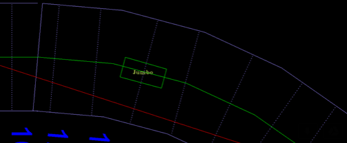
The lifters refer to the height of the Jumbo machine sides. These are lined up on both sides using the offset lines, as shown in the diagram below. The lifter height is normally 1.5 meters. However, when advancing on a decline/incline the height will change, but this change can be factored in when lining up. In the Laser Offset panel, Lifters is referring to the number of decimal places used when recording this number.
Reset Picking button
Clicking this forces you to reselect the starting and ending points from the screen. Normally, if a previous specification file has been opened, the same offset lines will be generated on the screen when the Apply button is clicked.
Apply button
Click this to begin selecting the starting and ending points from the screen.
Close/Save button
Click to save the specification file parameters and close the Laser Offsets module.
Cancel button
Close the module without saving.

