Section Definition
Define section views and save the specifications in a section file that can be called upon later.
Sections Toolbar
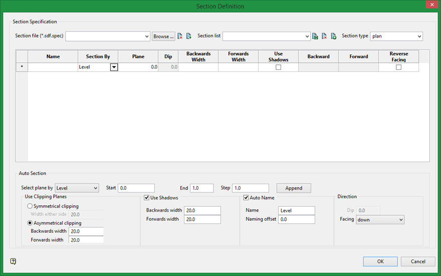
Section specification
Section file
Enter a name for the Selection file, or select the file from the drop-down.
Section list
Enter the name of the definition.
Section type
Select the section type.
Icons
|
|
New |
|
|
Save |
|
|
Save as |
|
|
Delete |
|
|
Delete list |
Table
Name
This is the identifier that will have a version. This name displays in the drop-down list on the Slice toolbar.
Section by
Easting: Select this option to enter a specific Easting value (X value). There are two ways to enter the Easting value, you can enter it directly into the text box, or you can click Digitise to select a point from the viewing window. The resulting section has a constant Easting (X) value. You will be facing in an easterly direction when defining the section view.
Northing: Select this option to enter a specific Northing value (Y value). There are two ways to enter the Northing value, you can enter it directly into the text box, or you can click Digitise to select a point from the viewing window. The resulting section has a constant Northing (Y) value.
Level Select this option to enter a specific Level value (Z value). There are two ways to enter the Level value, you can enter it directly in the text box, or you can click Digitise to select a point from the viewing window. The resulting section has a constant Level (Z) value.
Points : Select this option to define the plane by digitising two points and specifying the dip. To locate a point precisely, use the Snap to Objects ![]() or Snap to Points
or Snap to Points ![]() modes on the Digitise toolbar. Points may be snapped onto underlays, such as block model slices or triangulations. If you use Indicate mode
modes on the Digitise toolbar. Points may be snapped onto underlays, such as block model slices or triangulations. If you use Indicate mode ![]() to select the points, then the points have the current default Z value.
to select the points, then the points have the current default Z value.
Plane
Enter the distance that is moved each step when moving the section through space. To move the section through space, use the Slice Forward ![]() or Slice Backwards
or Slice Backwards ![]() icons on the Slice toolbar. Alternatively, you can select the Align View With Current Slicing Plane
icons on the Slice toolbar. Alternatively, you can select the Align View With Current Slicing Plane ![]() button on the Slice toolbar and use the up and down arrows to move through space. The default value is 0.
button on the Slice toolbar and use the up and down arrows to move through space. The default value is 0.
Dip
If you choose to select your plane by either a line segment or 2 points, then you must indicate a dip. The dip is the angle of the section from horizontal. Valid dip angles are between -90 and 90.
Backwards width
The view of your section will include everything behind your section.
Forwards width
The view of your section will include everything in front of your section.
Use shadows
Select this check box to shadow the data that falls outside the section. The default value is 20.0. The following options are only available when the Use Shadows check box is enabled.
Backward/Forwards
Specify the width of data that will be shadowed. The backwards width and the forwards width do not have to be the same value.
Reverse Facing
Select the Reverse Facing option if you want to reverse the facing direction of the predefined sections.
Auto section
Use Auto Section to automatically generate a set of sections that will be stored in the grid.
Select plane by
Select from Level, Northing and Easting. The default value is Level.
Start
Enter the starting point for automatically generated planes.
End
Enter the endpoint for automatically generated planes.
Step
Enter the distance that is moved each step when moving the section through space. The default value is 1.
Append
Select this option to automatically generate sections depending on the options entered in Auto section.
Use Clipping Planes
You can specify that the section is symmetrical (the same distance forwards and backward), or asymmetrical (different distance forward and backward). The default value is 20.0.
Use Shadows
Select this check box to shadow the data that falls outside the section. The default value is 20.0. The following options are only available when the Use Shadows check box is enabled.
Backward/Forwards width
Specify the width of data that will be shadowed. The backwards width and the forwards width do not have to be the same value.
Auto name
Select this check box to add the identifier Name for the set of sections. If you do not select the Auto name check box, you will need to enter a name in order to save the set of specifications sections.
Direction
Use the Direction option to specify and incorporate the direction in the naming process. This does not change the direction the sections are made, only the naming of the numbers.
Sections Toolbar
The Section Definition panel works in tandem with the Sections floating toolbar. The Sections floating toolbar can be located by right-clicking on the right-hand or bottom toolbar of the Vulcan workspace window to reveal the menu, and choose Sections.
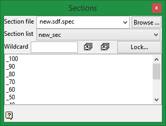
Section file
Select a section file from the drop-down list or browse for a file from the directory.
Set Identifier
Select the set identifier from the drop-down list. If only one set identifier has been created for the associated section file then it will automatically be listed.
Wildcard
Enter the name of the section view you wish to start with or enter an asterisk (*) which will be used as a wildcard to include everything.
Toggle through the list of views using the ![]() icons.
icons.
Lock / Unlock button
This button locks and unlocks a pivot point around which the Easting, Northing and Plan views will rotate.
For example, in the image below the red dot has been selected as the pivot point. The section showing for the Easting view will be the dark green. The section showing for the Northing will be the blue-green. The section showing for the Plan view will be the top surface. All sections have the pivot point in common.


|
Click to lock the coordinates of a pivot point. |

|
Click to unlock the coordinates of a pivot point. |
| [SPACEBAR] |
Alternates between Lock and Unlock. |
To take full advantage of this feature, we suggest setting customised hotkeys for Easting, Northing and plan view. (The Customise option can be found on the Workbench menu, then clicking on Customise.)
Instructions
Assign customised hotkeys for commands Switch to Easting, Switch to Northing and Switch to Plan Section, which are found in the View menu.
While in plan view, click the button then select a location for the pivot point.
To switch between section views, simply press the hotkeys.

