Point Label to Text
Use the Point Label to Text option to place point labels in a Vulcan layer, converting them into text objects and therefore making them printable. Placing the labels into a layer will also allow you to retain the labels onscreen while displaying other labels. The converted labels can also be saved with other design data.
Labels that are placed in a layer can be edited through using the options under the Design > Text Edit submenu.
Instructions
On the Analyse menu, point to Label, and then click Point Label to Text to display the Convert point data to text objects panel.
Layer
Select the layer that will be used to store the labels.
Description
Enter a description to further describe the contents of this layer. The maximum size is 80 alphanumeric characters. Spaces are allowed. If a description is not entered, then a default description will be used instead. If the chosen layer already has an assigned description, then this will be displayed when the layer is selected. Existing layer descriptions can be overwritten.
Settings tab
Select the check box for each of the object attributes to include in the specified layer.
To place the 2D coordinate values in the specified layer, enable both the X and Y check boxes. Enable the X, Y, and Z check boxes to place the 3D coordinate values in the specified layer.
Sequence
Select this option to label the points with their sequence number, that is, the order of digitising. Knowing the order of digitising or the location of the first and last points, may be necessary when, for example, appending objects.
Choosing the display the sequence number will require you to specify whether to label all points in the chosen object or just the first and last points.
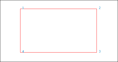
Figure 1: All Points Labelled with their Sequence Number
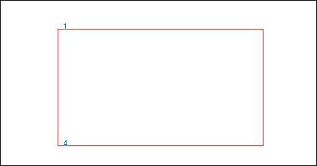
Figure 2: Start and End Points Labelled with their Sequence Number
Colour
The exported labels can be coloured using a colour chosen from the current colour table, or the labels can inherit the colour of the original object.
Attributes
Decimals
Enter the number of decimal places to display in the resulting labels. The maximum number of decimal places allowed in a single label is 6. The default number of decimal places is derived from the Miscellaneous section of the Tools > Preferences option.
All points
Select this option to display the sequence number, that is, the order of digitising, next to each point in the chosen object.
End points
Select this option to only display the sequence number for the first and last points in the chosen object.
The All points and End points options are only available when the Sequence check box has been enabled.
Add prefix
Select this check box to apply a prefix to each of the chosen labels.
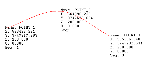
Figure 3: Apply prefixes to displayed labels.
Display points
Select this check box to display all of the points contained in the chosen object. The point settings under the Graphics section of the Tools > Preferences option will be used to control the size and appearance of the point markers.
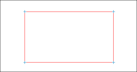
Figure 4: Displaying point positions
Display Style
This section is only available when one or more labels are being sent to a Vulcan layer.
Separate lines
Select this option to display each label on a separate line.
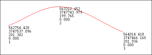
Figure 5: Displaying each label value on a separate line
Comma delimited
Select this option to display each label on the same line with a comma separating each value.
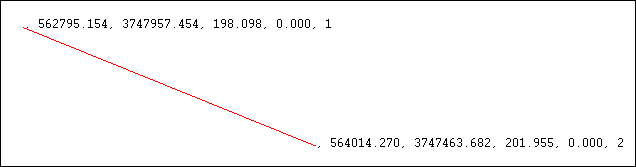
Figure 6: Displaying all label values on the same line
Font Settings tab
Label Font
Select the font type, that is, Fixed or True Type, followed by the required font from the drop-down list.
Fixed fonts, which are also known as non-transformable fonts, remain the same size when displayed onscreen regardless of the current zoom, and will always appear 'face on' (horizontal) regardless of the drafting angle. The drafting angle is only followed when a hard copy plot is produced. Unlike Fixed fonts, True Type fonts will resize as you zoom in/out, and the display will follow the angle set by the drafting angle.
Size of text on plot
Enter the size, in plotter units, of the text on the plot. The specified value will also be used to define the size of the point markers on the plot.
Drafting scale
Enter, as a ratio, the drafting scale, which is used in conjunction with the text size entered above.
If the text size is set to '0.10' (10 cm), and the drafting scale to '1:1250', then the text will appear on the screen the same size as an object that is 125 units long. Changing the scale, through either this option or the File > Plot > Plot All option to '1:1000' will result in the text appearing the same size as an object that is 100 units long. Changing the scale to '1:10 000' results in a text size of 1000 and so forth.
Drafting angle
Enter the angle at which the text block will appear. The resulting text will always be displayed horizontally when viewed onscreen, however, it will appear at the correct angle when plotted.
The drafting angle can be entered in decimal degrees; degrees minutes seconds (ddd.mm.ss) or gradians. To do so, select the appropriate angle format button and enter the drafting angle.
To enter a drafting angle of 50°, select the  button and enter '50' as the drafting angle.
Select a different angle format button to convert a value, for example 50° will become '55.555556' if the  button is selected.
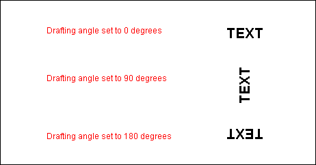
Figure 7: Drafting angle examples
Frame
Select this check box to place a frame or box around the displayed text. This check box can only be used when using the Fixed font style.
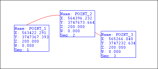
Figure 8: Framing text
The resulting frame is used for display purposes only and will not be plotted.
Click OK.
The Multiple Selection box is displayed for you to choose a selection method and select the labels.
The labels are then placed in the specified layer.

