3 PRISM METHOD
3.1 General Stope-Shape Framework
The Prism method is a different style of stope optimisation to the Slice method. In the Slice method the stope-shape framework is decomposed into individual geometric tubes based on the level and section dimension for the Vertical case, and the stope-shape (or sub-shape) is an optimisation over the width of the orebody, with a two stage process to
· Firstly define the seed-shape, and
· Secondly to anneal the final stope-shape.
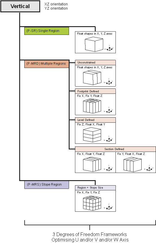
The Prism method also requires a stope-shape framework, but uses the decomposition of the framework extents to define sub-problems. The framework extent is subdivided in regular intervals, much like regular quadrilaterals, except that the subdivision is three dimensional rather than two dimensional, and each subdivided volume is referred to as aregion, whereas the Slice method subdivision is two dimensional to form atube. Figure 3‑1 summarises the stope framework hierarchical structure for the Prism method.
Stope-shapes are defined as a fixed set of shapes defined by the footprint and height, and the optimisation problem is defined as identifying a combination of non-overlapping stope-shapes from the set provided to maximise value or grade within each independent region.
Although the geometric formulation of the problem is different, the same evaluation options are available for cut-off, optimisation and reporting fields, inclusion/exclusion, filters etc. as applies to the Slice method.
The solution to the optimisation problem requires a mixed integer solver, and three are available:
·GLPKfor small problems, and
·CPLEXand Gurobi, commercial solvers that are appropriate for larger and faster solutions.
Licences must be separately purchased from the mining software suppliers for commercial solvers. It is important to remember that the Prism Method can create very large and difficult optimisation problems. The solution strategy should be to solve a coarse problem with minimal stope-shapes and decomposition of the framework, followed by progressive refinement of the framework, stope set and parameters used.
Figure 3 ‑ 1 Prism Method Stope-Shape Framework Hierarchical Structure
3.2 Prism Method Framework
Prism frameworks are not orientation specific but the X|Y|Zintervalsmust be regular. A gridincrementis also defined for each axis, within regions (i.e. sub-set volumes of the total Prism framework). Shapes from the stope-volume library will normally have dimensions that are an integer multiple of the grid increment and can result in stopes located at any grid increment.
The full framework definition may contain several regions that may be independent or contiguous abutments. This could be likened to a mine-site with mine sub-districts / areas / zones. The framework region(s) however must be rectangular in shape. Regions are user defined to make stoping geometric sense e.g. to span a group of levels or to span a group of sections or to span a group of levels and sections. The library of stope-volumes is applied to each region in turn with each region optimised independently. One use of regions is to force stope-volumes to honour say a regular level spacing or a regular section width (i.e. regular primary and secondary stopes).
The framework region(s) are further defined by regular grid increments in the X|Y|Z axes. This allows stopes-volumes to position with the bottom left hand corner at any grid increment, providing the stope-volume completely fits into the region. This gridding provides a stope framework for “floating” stope-shape volumes within each framework region.
Stopes from the library would typically have dimensions that are an integer multiple of the grid increment, otherwise gaps would occur between adjacent stopes. The size of the grid increments might in some cases be the minimum stope dimension.
As an example, using a region dimension of [100, 100, 250] (X|Y|Z), stope library dimensions defined by [30, 40, 10] for X and Y axes (minimum, maximum and step size) and [50,250,50] for the Z axis (minimum, maximum and step size) and a region grid increment of [20, 20, 50] (X|Y|Z) the following stope combinations are possible.
The possible X or Y axis combinations are: 1x40 (starting at either 0, 20, 40 or 60 grid interval in the region), 2x40 (starting at either 0/40, 0/60, 20/60 grid interval in the region), 1x30 (starting at either 0, 20, 40, 60 grid interval in the region), 2x30 (starting at either 0/40, 20/60 grid interval in the region), 3x30 (not possible due to 20 grid increment), 2x30 plus 1x40 (not possible due to 20 increment) in either X or Y axis.
The possible Z axis combinations are: 1x250 (starting at 0 grid interval in the region), 1x200 (starting at either 0, 50 grid interval in the region), 1x150 (starting at either 0, 50, 100 grid interval in the region), 1x100 (starting at either 0, 50, 100, 150 grid interval in the region), 2x100 (starting at 0/150 grid interval in the region), 1x50 (starting at either 0, 50, 100, 150, 200 grid interval in the region), 2x50 (starting at either 0/100, 0/150, 0/200, 50/150, 50/200, 100/200 grid interval in the region) and 3x50 (starting at 0, 100 and 200 grid intervals). Note that for the 2x100 case the 0/100 and 50/150 grid intervals starts are made redundant by the 1x200 case with 0 or 50 grid interval starts. This is because the set of largest stope-volumes is solved for.
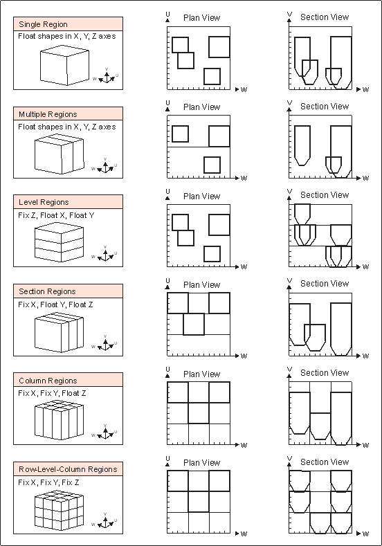
Figure 3 ‑2 illustrates the key aspects of the Prism Method for each of the different cases:
· total X|Y|Z framework extent,
· region extents defined by the interval (level, section, level and section),
· grid increments,
· stope locations (in a solution)
The stope locations are displayed in plan and section.
Figure 3 ‑ 2 Prism – Total Framework, Region Increment and Grid Increment Examples
3.3 Stope-shapes
The stope-shapes can be either:
· Rectangular (with square being a sub-set of rectangular), or
· Truncated Rectangular, shaped like an inverted milk-carton torepresenta trough-undercut for mucking extraction.
Specification of default strike angle and dip angle are not needed in thePrism Method, however, a framework orientation (i.e. XZ|YZ) is required to define the orientation of the trough undercut.
Annealing of stope-volumes is not available in the current implementation of SSO Version 2.
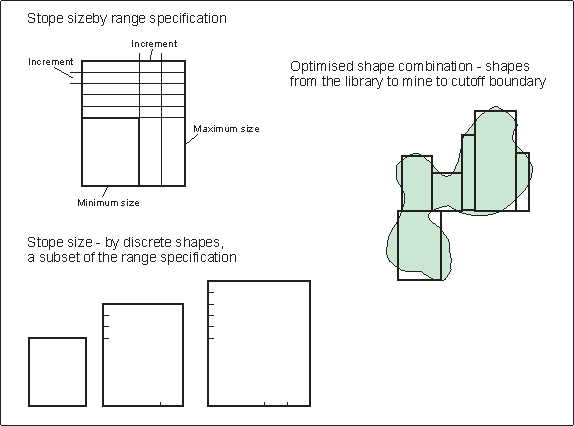
The stope-shape sizes in the stope-shape library can be specified quickly by using the minimum and maximum size and step increments for each axis, or the library can be explicitly defined giving specific axis dimensions for each stope-shape as depicted in Figure 3 ‑ 3 . The optimised shape combination can match the shape and position of stopes from the stope-shape library to the ore outline to maximise ore extraction, and total value.
Figure 3 ‑ 3 Shape Library or Defined Discrete Shapes
3.4 Trough Undercut
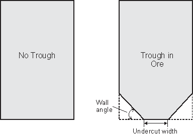
The SSO accounts for the waste dilution and/or ore loss regarding the shape of the trough-undercut during the optimisation process. The undercut provides an optimised rectangular stope-shape with the two bottom edges “bevelled” off parallel to the orientation axis to form the trough-undercut side walls.
The trough-undercut shape is defined by:
· Trough-undercut width at base
· Minimum trough-undercut wall angle from the base of the trough
· Position of the trough-undercut being either, left, centre or right (only centre is currently available in Version 2)
The two shape configurations are depicted in Figure 3 ‑ 4, and illustrate the parameters for the shaped prism trough-undercut stope-volume.
Figure 3 ‑ 4 Prism Shapes with and without Trough Undercut
3.5 Waste Pillar Separation
If two stopes do not abut then the optimisation solution must provide a minimum waste pillar between stope-shapes. Waste pillar separation between stope-volumes can be specified using a minimum value for the X and Y axis in the current implementation.
3.6 Advanced Parameters
3.6.1 MIP Solvers
A MIP solver is a mathematical optimisation program to solve integer or mixed integer optimisation. Two applications use the solver:
(1) PRISM method, which typically generates large MIP problems requiring a commercial grade solver,
(2) Sub-stope optimisation, for which only small MIP problems are generated.
Three MIP solvers are supported:
(1) GLPK, a free solver, suitable for small problems
(2) CPLEX 12.6, a commercial grade solver
(3) GUROBI 5.6, a commercial grade solver from the original developers of CPLEX.
The CPLEX MIP solver provides faster processing and handles larger run-matrices. CPLEX outperforms Gurobi for Prism optimisations in the current release.
3.6.2 Rectangular and Shaped Stopes
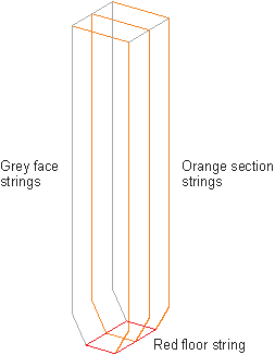
The Prism strings produced are as depicted in Figure 3 ‑ 5 and include:
· the trough profile face strings (when the undercut trough option is enabled),
· the section strings,
· the intermediate section string(s) (when this option is enabled),
· the floor string.
Figure 3 ‑ 5 Strings for Undercut Trough Shaped Stopes
3.6.3 Stope Sublevel Constraints
By default the position of stopes is only constrained by the framework extents, the region boundaries (defined by the axis intervals) and the grid increment. The location of sublevels is not automatically constrained, and this solution provides the first estimate of the optimal set of stope dimensions to maximise value or metal. A visual inspection of the solution might assist to identify optimal level locations.
The combination of stope-shapes that can be considered within each region can be further constrained by forcing the sublevel locations to be applied in the solution. Using these “common sublevel” options is described in the following sub-sections. Note that solving with these additional options can result in an exponential increase in the problem size, and long run times, even with a commercial solver. Note that the computer operating system swap-space, paging file size or virtual memory may need to be increased (to the available physical memory size) to prevent memory issues. Configure the system with a large amount of physical memory (RAM) if possible, as this can significantly improve runtime performance of the MIP solver.
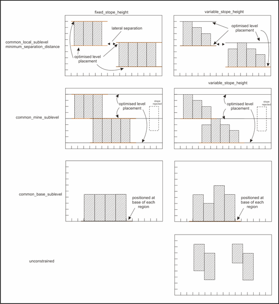
Figure 3 ‑ 6 illustrates the various common sublevel constraint options.
3.6.3.1 Stope Sublevel – “common_base_sublevel”
This function anchors the stope floor levels to each region’s minimum Z value.
3.6.3.2 Stope Sublevel – “common_mine_sublevel”
This function requires that all stopes honour the set of levels found in the optimisation run (i.e. selects the best of feasible solutions). For example, a stope optimisation solution where one stope is located at say 10m above a common-level (of say 40m) shared by other stopes would not be feasible or allowed.
3.6.3.3 Stope Sublevel – “common_local_sublevel”
This function allows levels to vary within a region, but vertically over-lapping stopes within a minimum horizontal separation distance must have the same floor level (i.e. adjacent stopes that overlap in the vertical sense cannot have an offset in the floor, although they can optionally be displaced from a regular grid in the X,Y space). The effect is to cluster stopes into groups with each group having a shared set of sublevels.
3.6.3.4 Stope Sublevel – “variable_stope_height”
This is a function modifier for the “common_mine_sublevel” and “common_base_sublevel” options. Enabling this sub-option allows variable height stopes to be created between sublevels (e.g. it allows the creation of say “half-height”, “three quarter height” if these stope-shape options are specified in the shape library). The results from this option are illustrated on the right hand side in Figure 3 ‑ 6.
Figure 3 ‑ 6 Prism – Sublevel Constraints for Stope-Shapes
3.6.4 Validation Test Cell
For small test runs, an individual region can be selected by defining the index to the Region (like the QUAD number for Slice except that this index is a three dimensional index). Alternatively a smaller test problem can be run by specifying one or more three dimensional (x,y,z) coordinates which will be used to select the Region number that encloses the point(s), and only the subset of feasible stope-shapes that enclose this coordinate will be selected for the optimisation. While the latter is not automatically part of a feasible solution to the full problem, the solution can be inspected and it is still a useful verification that the Prism process has been formulated as expected.
Only stope-shapes that overlap with one or more of the coordinates will be processed for the optimisation. Note however, that some options will require the full set of stope-volume shapes to provide a meaningful optimisation, e.g. if applying the “common_mine_sublevel” or “common_local_sublevel” options then the results are meaningless without the full complement of possible stope-shapes.
3.6.5 Prism Optimisation Exceptions
All optimisation options as detailed in Section 3.7 are available in thePrism Methodwith the following exceptions:
· Precise evaluation is automatically used. Fast evaluation is not used because annealing is not yet supported
· Model discretisation is not enabled. The orebodies will typically be massive or wide, stopes large, and so there is not the model sampling/cell accuracy issue as experienced with stope-shapes needing to honour geological wireframes in annealing for slice methods.
· The Mined-out model can be output, but without discretisation it can be a little coarse, and may not sufficiently capture the detail of the stope-shape geometry. Only mined out cells can be output.
· No output of sub-economic stopes, as the optimisation only generates economic stopes.
· The Position Counter in Stope Naming leverages the section, level and transverse position from the stope shape framework definition, and consequently will have limited applicability to Prism "Region" frameworks.
3.7 Good Practice - Tips and Procedures
Version 2 is the first release of the Prism method, and hence it has been applied to a limited number of case studies.
The most common difficulty will be that the run times are too long, or the run does not finish. The complexity of the optimisation problem is directly related to the number of feasible stope-shapes that need to be considered, and how tightly they are grouped. There can be a very large number of high value feasible solutions but finding the best can involve a deep search of the solution space. The best may however be only a very small improvement on many other solutions.
Some suggestions to consider:
(1)Choice of Solver
The GLPK solver can solve small test problems, but a commercial solver will be required for large problems.
(2)Choice of Region size
Reducing the region size or constraining the search to a subdivision of the space (by section, level or column) can be very effective. This subdivision of the search space is recommended because the solutions will be very fast.
(3)Choice of grid increment
Reducing the grid increment in each of the three dimensions can have a dramatic effect on the problem size. The initial grid increment could be the stope size on that axis to get a quick run and then the grid increment could continue to be halved. If the stope footprint was 20x20m then the first run might have an increment of 20m, then the next 10m then 5m, etc.
(4)Choice of Optimisation Parameters

