Create
Define Mining Strips on Dragline Sections
Use the Create option to create mining strips on your Dragline sections. Strips can be created on the fly, or from an existing strip plan layout. Prior to creating strips, you must have previously created your section arrows (refer to the Create option under the Dragline > Sections submenu).
Dragline strips are dimension objects, created in each dragline layer with the name:
STP_<strip_number>
On each section, the strip number starts at 1 and continues to the number of strips defined on the section.
Instructions
On the Dragline menu, point to Strips, and then click Create to display the Create strips panel.
If a Dragline specifications file (.rsp) was not opened prior to selecting this option, then the Open Dragline Specification panel displays first.
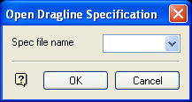
Open Dragline Specification panel
Spec file name
Enter, or select from the drop-down list, the <spec_file_id> part of the dragline specifications file name. The maximum size is 6 alphanumeric characters. Selecting a name from the drop-down list will open an existing specifications file. Entering a new name will create a new specifications file.
Click OK.
The Create strips dialog box contains the following options:
Fixed interval
Select this option to generate constant width strips, starting from a strip origin point. The instructions include examples.
Intersection
Select this option to generate strips where the dragline section planes intersect with a predefined strip plan layout.
Fixed Interval
The Creation method dialog box displays.
Apply to current section only
This method of strip creation creates strips only on the current section (refer to the Set Current option). You will be prompted to digitise the strip origin position. The origin must be a point along the current dragline section.
Once you have indicated the strip origin position, the Fixed Interval Strips panel displays.
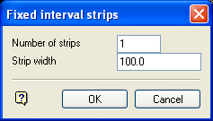
Number of strips
Enter the number of strips that will be generated along the dragline section. These strips will start at the origin position and continue in the direction of the section arrow.
Strip width
Enter the width of each strip measured along the dragline section.

Figure 1: Creating Fixed Interval Strips on the Current Section
You can use the View Current Section option to view the result of this method of strip creation.
Apply to all sections using common origin
This method of strip creation is similar to the Apply to current section only option. Here, however, the strip origin you digitise, is projected onto all the other section planes as well, and strips are created on all sections.
Apply to all sections using intersecting baseline
This method of strip creation, requires a previously created baseline string. Upon selection of the baseline, it is intersected with the dragline section planes, to define a strip origin on each section.

Figure 2: Creating Fixed Interval Strips using an Intersecting Baseline
Intersection
Select this option to generate strips where the dragline section planes intersect with a predefined strip plan layout. One way of creating such a strip plan layout is to use the Open Pit > Pit Layout > Offset option.
Upon selection of this option, the Multiple Selection box displays, so that the strip plan objects can be selected by category. When the selection has been made, dragline strips will be created at each intersection pair that is found.
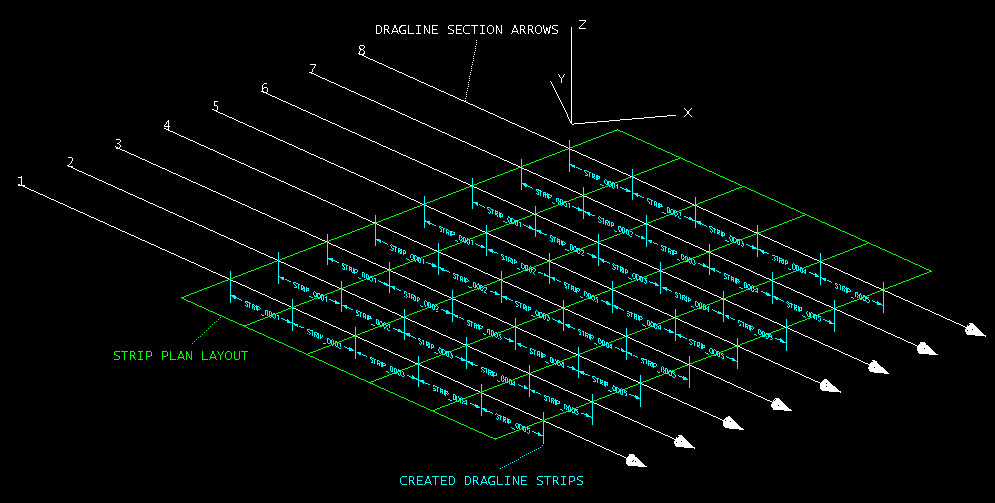
Figure 3: Creating Strips by Intersecting Section Planes with a Strip Plan Layout

