Hole Clearance Check
This option is used to indicate any holes in the blast which are not separated by at least a required minimum distance. The distance tolerance is checked only between the explosive-charged parts of the holes for combinations of pairs of holes in the blast. Where the specified tolerance for separation distance is compromised a line marker is drawn at the MINIMUM SEPARATION position between two holes. If the holes are parallel and alongside (similar RLs), the marker will be drawn at the highest perpendicular position of separation - typically this will be at the base of stemming for one or both of the holes.
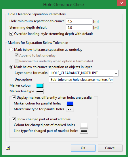
Prior to using this tool, load the blast(s) to be checked. The check is performed on a per blast basis. As each blast is selected, the following panel is displayed to specify the requirements to check that blast.
Instructions
Click the Hole Clearance Check ![]() icon on the Drill and Blast toolbar.
icon on the Drill and Blast toolbar.
Or
On the Drill and Blast menu, point to Analysis and Reporting, and then click Hole Clearance Check.

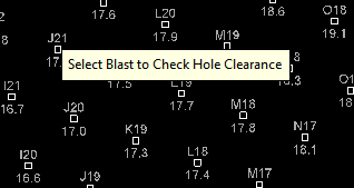
Select the blast of interest.
After selecting the blast, the blast will grey out and the Hole Clearance Check panel will load.

Hole Clearance Separation Parameters
This section of the panel defines the requirements for the minimum distance check.
Note: All measurements will be shown in the current Vulcan-window units.
Hole minimum separation tolerance
Enter the minimum allowed separation distance between the explosive-charged parts of the blast holes. If any pair of holes compromises this distance, the minimum distance between those holes will be marked as per Markers for Separation Below Tolerance on this panel, and a report line to that effect will be written to the Vulcan Report Window.
Stemming depth default
The stemming depth defines the downhole depth where the charge starts. Above this depth the hole contains inert stemming material and will not be considered in the hole-separation checking. The stemming depth may be obtained individually for each hole from the loading-style information present on that hole, if the holes have loading-style information
Loading-style is optional. See Drill and Blast > Specifications setup for details.
Alternatively, a default stemming depth can be used to override this for all holes in the blast. If a hole is too short for the stemming depth specified it will be ignored in the check and a report line sent to the Vulcan Report Window to this effect.
Override loading-style stemming depth with default
Check this option to override loading-style stemming depth with default stemming depth for all holes in the blast.
The panel default is for this is set to override with the default stemming depth. If the option is not ticked, the system will then attempt to determine each hole’s stemming depth from the loading style information (using the top of the explosive loading as the stemming depth).
However, it is still important to specify a meaningful default value when not overriding.
If the optional loading style is not present on a hole the default value will be used for that hole. Likewise, if the loading style is inappropriate for the hole (e.g. explosive depth is too great for hole depth), or incompletely specified, the override default will be used. In all of these cases, a message will be displayed informing the user, reporting all instances where the default depth was needed and requesting verification to continue.
Note: To check separation over the entire hole length, specify the default stemming depth as 0.0 and check on Override loading-style stemming depth with default.
Markers for Separation Below Tolerance
Markers for separation below tolerance may be displayed either as an underlay (visible for the current Vulcan session only) or may be saved as objects in a design layer (which can be saved to the DGD).
Mark below-tolerance separation as underlay
Toggle to this option to display below-tolerance separation markers as an underlay. The display is not able to be saved for future reference.
Append to last underlay
Check this option to append the markers for each blast selected for checking in the operation to the same underlay. If this box is unchecked, a new underlay will be created for each individual blast checked.
Remove this underlay when option is terminated
Check this option to remove the underlay of markers from the Vulcan window when Hole Clearance Check option is terminated.
Mark below-tolerance separation as objects in layer
Toggle this option to display below-tolerance separation markers as individual objects in a design layer. This layer can be saved to the design database and redisplayed for reference as required.
Layer name for marks
The default layer name is in the form of: HOLE_CLEARANCE_<blast name>. Alternatively, enter the preferred layer name.
If the layer name specified already exists, you will be prompted to overwrite, replace or append to it (if it is loaded). In the event that the layer is appended to, the original description will not be replaced with the new one.
The objects created will have the following characteristics:
-
Two connected points: The position on each hole?stick of the minimum separation.
-
Name in the form: <hole_name1>?<hole_name2> for the two holes in proximity.
-
Feature: HOLE_CHECK
-
Group in the form: CLR_CHK:<blast_name>
-
Description in the form: Closest separation marker of holes <name1> and <name2> will be followed by (Holes are parallel) for parallel holes.
-
Colour and line type: As specified below.
-
The description (not Feature and Group) will be localised for different languages.
Description
The default layer description is in the form Sub-tolerance hole clearance markers for blast <blast name>. Alternatively, enter the preferred layer description.
Marker colour
Click on the colour to access the colour palette. Select the colour for the markers.
Marker line type
Click on the line type button to access the line type palette. Select the line type for the markers.
Display markers differently when holes are parallel
All markers for below tolerance separation will appear as specified above unless this option is ticked.
Check this option to be able to distinguish the parallel holes which are below the required separation distance. This may be useful because parallel holes have the same minimum separation over their whole length and not just at the one arbitrary position shown.
If checked you can then specify separate colour and/or line-type for this markers.
Marker colour for parallel holes
Click on the colour to access the colour palette. Select the colour for markers for parallel holes.
Marker line type for parallel holes
Click on the line type button to access the line type palette. Select the line type for markers for parallel holes.
Show charged part of marked holes
Check this option to show graphically the charged parts of the hole below the stemming depth. This may be useful as visual confirmation that the correct sections of the holes is being checked.
Colour for charged part of marked holes
Click on the colour to access the colour palette. Select the colour that will apply to only the charged part of each marked hole.
Line type for charged part of marked holes
Click on the line type button to access the line type palette. Select the line type that will apply to only the charged part of each marked hole.
If design objects are being created for the charged parts of the hole, they will have the following characteristics:
-
Two connected points: The stemming depth point and the bottom of the hole.
-
Name in the form: CHARGED_PART:_<hole_name>
-
Feature: HOLE_CHARG (max 10 chars)
-
Group in the form: CHARGED:<blast_name>
-
Description in the form: Charged section of hole <hole_name> below stemming depth.
-
Colour and line type: As specified above.
The description (not Feature and Group) will be localised for different languages

