Set Up Stereonet
Set the display attributes
The Set Up Stereonet option to specify the display attributes for stereonets.
Figure 1: Stereonet Setup
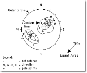
The diagram shows, for contoured data, the net notches, outer circle and title to highlight the distribution of pole points and associated contours.
![]() Tip
Tip
The Set Up Stereonet option should be used to make the stereonets visible before using the Transfer or Plot options (under the Analysis and Utilities submenus respectively).
Instructions
- Select Geotech menu
- Select Display submenu
- Select Set Up Stereonet option
The following panel displays.
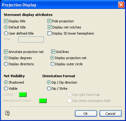
Projection Display panel
Stereonet display attributes
Display title
Select this check box to display the stereonet title. You then have the choice of either the Default title (Equal Area or Equal Angle) or a User defined title. If User defined title is selected, then enter the desired title in the box provided. The user defined title may be a maximum of 30 characters.
Pole projection
Select this check box to display data using the pole projection standard method.
Display net notches
Select this check box to display notches around the circumference of the stereonet at one degree intervals.
Display 3D lower hemisphere
Select this check box to display the lower hemisphere of the stereonet. This may be useful when displaying structural data as 3D plane representations (see the description of 3D plane representations in the Load To Stereonet option).
Annotate projection net
Select this check box to annotate the edge of the stereonet with either degrees or the four cardinal directions, i.e. N S E W. The annotations are in scalable fonts, and can be changed (for example rescalable) using the regular Vulcan text editing options. Select the button for the type of annotation required.
Grid Lines
Select this check box to display stereonet grid lines. The Display projection net option displays the outer circle and the projection net. The Display outer circle option will display the outer circle only. This option may be useful when displaying contour information.
Net Visibility
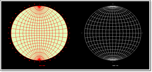
This section of the panel allows you to set the visibility of the stereonet. Stereonets can be shadowed or visible. Selecting the Visible option will allow you to assign a stereonet colour and a background colour. The colours will be selected from your current colour table.
Figure 2: Stereonet Visibility and Colouring
Orientation Format
This section of the panel allows you to select the format for point orientation. The options available are for Dip/Dip direction and Dip/Strike.
If Dip/Strike is selected, then the options for Use right hand rule and Use Strike orientation field are activated. Check the check boxes required. The strike orientation field (ORIENT) is set in the structural database. This field typically contains information such as N, S, E, W, NW, NE,
Select OK.
Select the stereonet that will use the configured display settings. Right-click with the mouse to return to the Projection Display panel.

