Load To Stereonet
Load structural data as projections
The Load To Stereonet option to load and display data, from either the structural database or the Stereonets Window, as projected objects in the Primary Window.
![]() Note
Note
Instructions
- Select Geotech menu
- Select Display submenu
- Select Load To Stereonet option
The following panel displays. If a structural database has not been opened prior to selecting this option, then the Open Structural Database panel displays first.
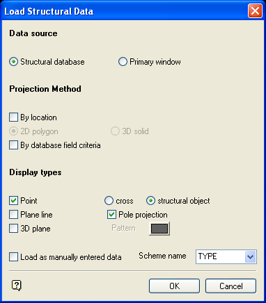
Load Structural Data panel
Data source
Structural database
Select this option if you want the structural data to be loaded directly from the structural database.
Primary Window
Select this option if you want the structural data to be transferred and loaded from the Primary Window.
Projection Method
Display types
The data to be loaded can be displayed as points, plane lines and 3D planes.
Point
Points are stored as single objects and coloured (like the 3D data) according to the values set up in the Set Up 3D Display option. The points can be displayed as crosses or structural symbols. If you select structural object, then a geotech PROJECTION symbol displays.
Pole projection
Select this check box to display the selected points, from the database or Primary Window, as pole points on the stereonet. If this box is not ticked, then the points displayed will lie in the projection plane.
Plane line
Plane lines are also stored as single objects, and coloured to the value defined in the Set Up 3D Display option. Plane lines are also called "great circle" projections.
3D plane
The 3D plane representations are not projections, but true 3D representations of the structural data. These should be viewed in relation to the 3D lower hemisphere. A pattern for the 3D planes is selected from a patterns file.
Load as manually entered data
Select this check box to load the data as manually created structure objects, i.e. without a link to the structural database. This allows you to load, for example, all the faults from a structural database as manual and some other type as normal thus ending up with data in two different layers which can then be manipulated separately.
![]() Note
Note
Manually entered objects or objects loaded as such show only the basic attributes of the structure object when using the Identify option (under the Geotech > Analysis submenu). Any database information is not shown because there is no association with the database.
Scheme name
The colour legend to be used for the data to be loaded can either be manually entered or selected from the drop-down list. The drop-down list contains colour legends from the Geotech colour scheme.
Select OK.
The Limited Selection Criteria panel is then displayed. However, if the By database field criteria checkbox was ticked, then the Selection Criteria Entry panel displays instead. Refer to the Load To 3D option for descriptions on both of these panels.
Once these panels have been completed, you are then prompted to select the stereonet to load. To select the stereonet to load into, pick a point located in the projection net. Once selected, the loading process is then started.
If you are loading from the Primary Window, then you are moved to the Primary Window (if not already there) and prompted to select a layer to select the structural data from.
![]() Note
Note
Only visible structural data is transferred, including manually entered data (entered through the Slope option).

