Database Import
Import drillhole data into a structural database
The Database Import option to load structural data from a drillhole database into a structural database.
The open drillhole database will be used as the source of the drillhole data. The holes don't need to be displayed from which structural data will be imported. The (X, Y, Z) location of each structure is calculated based on its down-hole survey position in the drillhole. This means that the holes must be de-surveyed, i.e. a .dsr file must exist.
Also, the currently open geotech database will be used as the location in which to store the results of the import. If no geotechnical database is open, then the Open Structural Database panel displays.
The drillhole database must have the specified structural table type in its design and every field in that structural table (in the drillhole database design) must be present in the structural database. The field name AREA in the HEADER table of the structural database must have at least one value; there must also be at least one value for the field name TYPE in the GEOTEC table. To set this up you can use the Isis Database Editor.
The name of the depth field is required so that the co-ordinates for each structure can be calculated using the down-hole depth values. If the angles for each structure in the geology database are relative to the orientation of the drillhole core (rather than being true dip and true direction), then a conversion to true dip and true dip-direction can be performed.
Instructions
On the Geotech menu, point to Utilities, then click Database Import.
The following panel displays. If the appropriate databases have not been opened prior to selecting this option, then the Open Geological Database panel and/or the Open Structural Database panel will be displayed first.
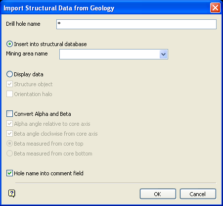
Import Structural Data from Geology panel
Drill hole name
Enter the name of the drillhole whose structural data is to be imported into a structural database. The * (multiple character) wildcard may be used to load multiple drillholes.
Structural Data can be inserted directly into the currently open structural database or it can be displayed as manually entered data
Insert into structural database
Select this option to insert structural data directly into the currently open structural database. The new GEOTEC records containing the imported structural data will be inserted after the HEADER record containing the mining area name. The search for the mining area in the structural database is case sensitive, that is M is different from m. The mining area name that you enter must exist in the AREA field of the HEADER record.
This option cannot be undone, it is important that the data is correct before modifying the database. Once the import is complete, the database should be checked using Isis.
Display Data
Select this option to load the structural data as manually entered data. The structural database is not modified in any way. This option is recommended as a first step to verify that the data is being interpreted correctly before inserting it into the structural database. Refer to the Load To 3D option (under the Geotech > Display submenu) for a full explanation on the display types, i.e. structural object, orientation halo.
Geological Database Attributes
Structural record name
Enter the name of the record in the drillhole database that contains the structural data to be imported. Every field in this record must correspond in both name and type to a field in the structural database.
Depth field name
Enter the name of the field to be used to obtain the down-hole depth values for calculating the co-ordinates for each structure.
Convert Alpha and Beta
Select this check box if you have measured alpha and beta (or delta) angles for each structure and you want Vulcan to calculate the dip and dip-direction of the structure from these angles.
Some people use the beta angle for lineation measurements, this module does not support conversion of lineation measurements, such as mineral elongation, intersection lineation etc. If you require this, then please contact your local Maptek office.
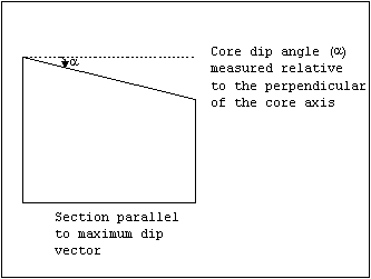
Figure 1: Alpha Angle/Section View
The following options are available when using the Convert Alpha and Beta option:
Alpha/Beta field name
Enter the name of the fields to be used to obtain the alpha and beta values.
Angle relative to core axis
Ticking this checkbox causes the alpha value to be the angle between the core axis and the structure. Therefore, for a vertical hole, an alpha value of 0 indicates a vertical structure (dip = 0°) and an alpha value of 90 indicates a horizontall structure (dip = 90°). Leaving this box unticked will result in the alpha angles being measured relative to the plane perpendicular to the core axis.
Angle clockwise from core axis
The beta value corresponds to the angle between the reference line and the bottom of the structure. This is measured in a clockwise direction when looking along the core in the direction of drilling, from a reference line on the top of the hole/core.
Therefore, for a vertical hole, a beta value of 0 indicates a dip direction of 0 degrees and a beta value of 90° indicates a dip direction value of 90° (see Diagram 2 and 3). Leaving this checkbox unticked will result in the beta angle being measured in an anticlockwise direction.
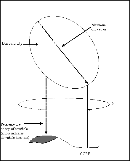
2- Beta/Sectional View
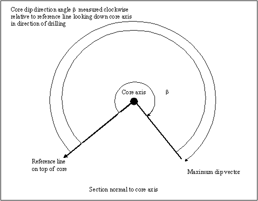
Figure 2: Beta/Plan View
The Beta measured from core top and Beta measured from core bottom options allow you to specify whether the reference line for Beta angles is at the top or bottom of the core.
Hole name into comment field
Select this check box to place the hole ID, i.e. the drillhole name, in the comment field.
Select OK.
The drillhole data is then loaded.

