Compare Stratigraphic Models
Use this option to easily compare different versions of structure grids.
On the Grid Calc menu, point to Integrated Stratigraphic Modelling, then click Compare Stratigraphic Models to open the following interface.
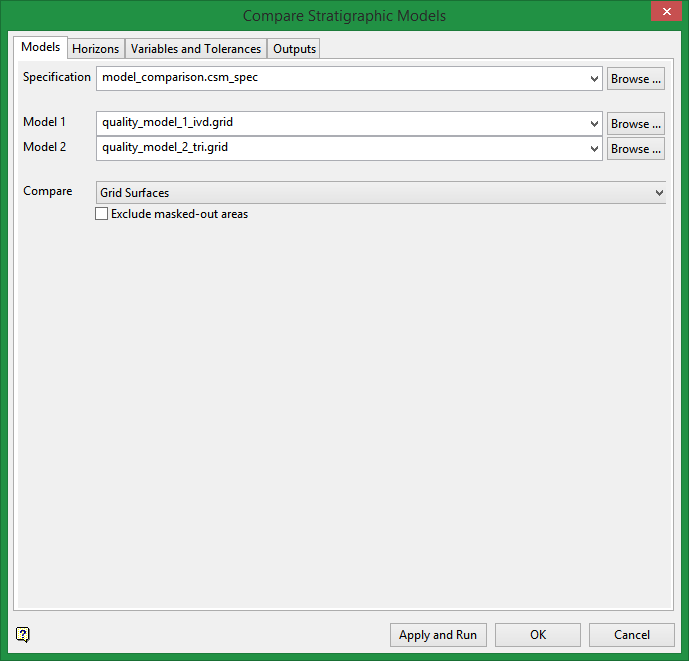
Specification
Enter a name for a new specification file in which to store the settings, select an existing file from the drop-down list if it is located in the current working folder, or click Browse to search for it in another location. The extension (.csm_spec) will automatically be added to a new filename.
Model 1 and Model 2
Select the two models that will be compared against each other.
Compare
Select whether to compare grid surfaces or triangulation surfaces.
Exclude masked-out areas
If there are areas that have been masked out and you wish to exclude them from the comparison, select this option.
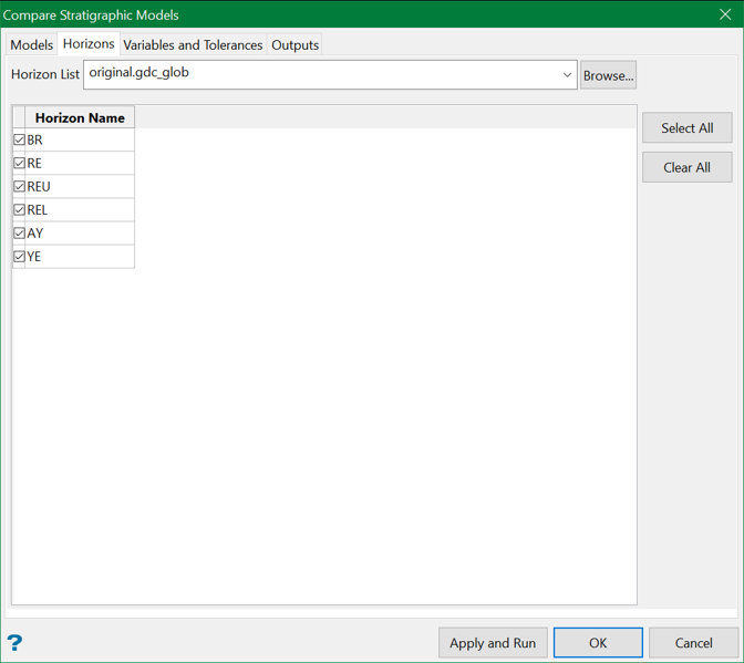
Horizon List
Select the (.gdc.glob) file that contains the horizons.
Horizon Name
Select each horizon that you want to use in the comparison.
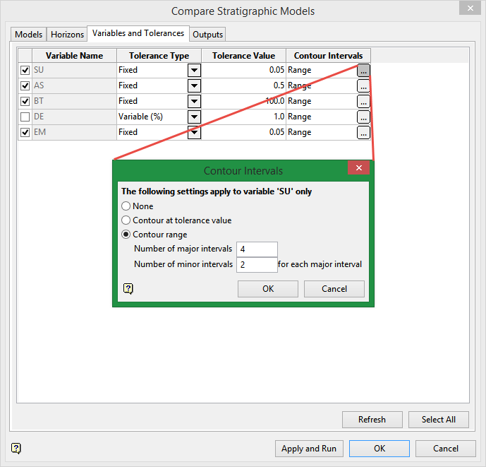
Variable Name
Automatically populated.
Tolerance Type
Select between Variable or Fixed.
Tolerance Value
Enter a value between 0.0 and 100.0.
Contour Intervals
Click the  button to display the Contour Intervals panel.
Note: Panel settings only apply to the variable named in the same row. It is NOT a universal setting.
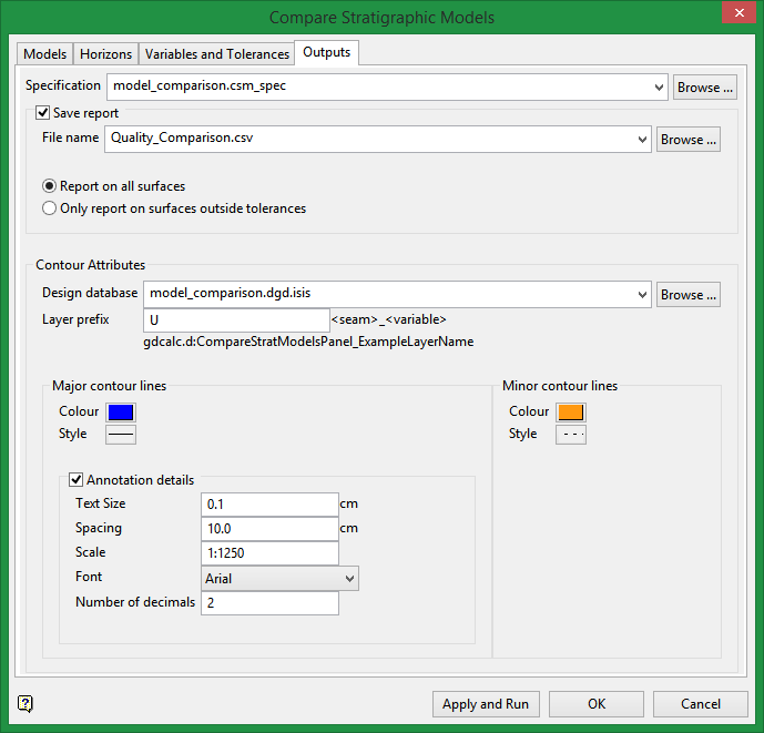
Specification
Enter a name for a new specification file, or select an existing file from the drop-down list. Browse for one in another folder by clicking the Browse button.
Save report
Save the results of the report by entering the name of a new file with the extension, or select an existing file from the drop-down list. Browse for one in another folder by clicking the Browse button.
Report on all surfaces
Select this option if you wish to see a report on all surfaces regardless of whether they were within or outside of tolerance parameters.
Only report on surfaces outside tolerances
Select this option if you only wish to see a report on those surfaces that are outside the tolerance parameters.
Contour Attributes
Design database
Select the design database from the drop-down list, or browse for it by clicking the Browse button.
Layer prefix
Enter a layer prefix that will be added to the name.
Major/Minor contour lines
Select the colour and style of the lines that will delineate where discrepancies exist between the two models.
Annotation details
Text Size
Enter text size in centimetres.
Spacing
Enter the spacing between annotations.
Scale
Enter, as a ratio, the drafting scale, which is used in conjunction with the text size entered above.
For example: If the text size is set to '0.10' (10 cm), and the drafting scale to '1:1250', then the text will appear on the screen the same size as an object that is 125 units long. Changing the scale, through either this option or the File > Plot > Plot All option to '1:1000' will result in the text appearing the same size as an object that is 100 units long. Changing the scale to ' 1:10 000' results in a text size of 1000 and so forth.
Font
Select the required font from the drop-down list.
Number of decimals
Enter the number of decimals places.
Click Apply and Run to compare the models.
Click OK to save the parameters without comparing the models.
Click Cancel to exit the panel without saving.

