Database Elements
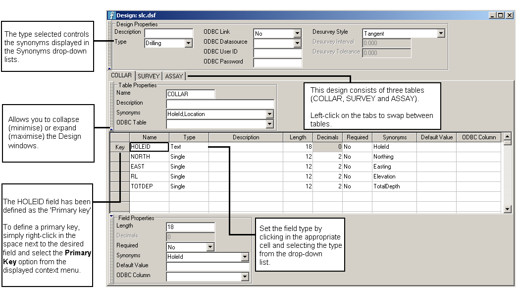
The diagram below is the design view of an Isis file. You can toggle between the design view and the database view by using the options under the View menu. The tables in this design are displayed as Notebooks rather than Multiple Windows. It is possible to alter this setting by using the Preferences option (under the Edit menu). However, you will need to close and open the database for the display to change.
Tables
A design is divided into tables, each table is designed to cater for a particular type of information. For example, a COLLAR table may hold all the information relating to drillhole collar location and length, whereas the ASSAY table may hold all the information relating to the drillhole assayed samples. The table must be unique in the design. The first table is assumed to be the header table.
The options under the Table menu will allow you to insert, append, delete tables.
Records
A record is a collection of data about a particular item. A record is represented as a row in the table.
Fields
Each table is divided into fields, represented by columns. Each field name is unique in a particular table, although you may use the same field on different tables in the same design. Fields contain information about the type of data that will be stored in the database.
Fields can be one of four types of data; text, integer, single and double.
| Data Type | Description |
|---|---|
| Text | A field that contains alphanumeric characters. |
| Integer | A field that contains only integer values. |
| Single | A field that contains real numbers that consist of fewer than seven (7) significant figures, that is, 12345600000. |
| Double | A field that contains real numbers than consist of seven (7) or greater significant figures, that is, 123456.789. |
To specify the field type, click in the Type column and select the type from the drop-down list.
Fields in the Header table (this is assumed to be the first table) can be defined as key fields, note singles and doubles cannot be key fields. This will reduce data entry as all of the other tables will not require this field as it is considered to be the common link. Key fields will speed up database access and calculations.
For most designs you may have up to and including 15 key fields in the header table. However, DSR designs can only have one key field. To define a key field, right-click in the label to the left of the row and select Primary Key from the displayed context menu. Please note that all designs must be created with at least one key field.
Note: Text type fields will be truncated to 80 alphanumeric characters when the table definition exceeds 512 characters.
Desurvey
You can create a DSR (Downhole Spatial Representation) database in the format of a downhole X, Y, Z coordinate for each survey point, as well as relative shifts in each direction down the hole. The DSR database is required by library style drillhole databases to provide desurvey information. Headered (including ODBC Link) style databases store this information in the header.
The resulting file is <proj><odi>.dsr, an index file is also created (<proj><odi>.dsx). In addition a <proj><odi><dsn>.chk file is generated that contains the data groups and record numbers. This can be used to check the created desurvey database.
Note: Synonyms are required. Any changes to the database require a new DSR database to be created.
Desurvey style - azimuth and dip at the depth
Five methods are available to give azimuth and dip values at various depths down the hole:
- Tangent
- Tangent With Length
- Tangent With Intervals
- Segment Following
- Segment Preceding
Tangent Values
In the Tangent option, the azimuth and dip occur at the given depths. This means that they describe the tangent at that point of the drill hole. Although we represent drillholes using straight lines, they are actually continuous curves. The survey instrument measures the azimuth and dip at a given point, it reports the value observed at that particular point in space.
For the standard tangent method, the assumption is that the survey record defines the centre of a segment of the given dip and azimuth passing through the depth defined (the tangent). So if you look at the drillhole in Vulcan, you will se inflection points created at the midpoints of the survey record depths. That is, the tangent goes half way from the previous interval to half way to the next interval.
Tangent With Length
This option to define a length (L). This will then be used to create a new survey entry every L metres along the hole depth, and compute the co-ordinates using the averages of the survey information (inclination, bearing and depth) derived from the previous entry and the next entry. For example, if the original surveys were at 0m, 50m and 100m, and the Interval Length was set to 10m, the survey inflection points would be calculated at 0m, 10m, 20m, 30m, 40m, 50m, 60m etc.
The tolerance option is used when the original survey is not at a precise interval, for example, 53m. It is possible then to set the tolerance to say 4m, to ensure that all surveys in 4 metres are calculated. Generating a large number of inflection points between surveys, does allow the hole to "curve" better, but may slow down the loading of holes.
Tangent With Interval
This option to specify the number of points to add between the two downhole surveys. Given the number of segmentations (N), the segment between two consecutive surveys will be cut into N sub-segments. A new DSR entry will be calculated for each of the new sub-segments. For example, if the original surveys were at 0m, 50m, 75m and so on, and the step interval was set to 10, then inflection points would be generated at 5.0m, 10m, 15m, 20m, 25m, 30m, 35m, 40m, 45m, 50m, 52.5m, 55m, 57.5m, 60m, 62.5m, 65m...75m, etc.
Segment Following
In the Segment Following option, the azimuth and dip describes the drillhole interval following the given depths. In the example, the azimuth of 120° and dip of -90° apply to the interval from the 0 metres through to 10 metres depth.
Since drillholes are not really composed of straight segments going 10m, at an azimuth of 120° and a dip of -90°, this type of data is processed data, as opposed to observed data. It does not describe the real world, but has been processed for easier handling. Given this information, it is easy to draw a picture.
| Depth | Azimuth | Dip |
|---|---|---|
| 0 | 120° | -90° |
| 10 | 122° | -45° |
| 20 | 124° | 0° |
Segment Preceding
The last option, Segment Preceding, describes a similar picture to above, although this time, the azimuth and dip refer to the drillhole interval preceding the given depths. In the example, the azimuth of 120° and the dip of -90° apply to the drillhole segment preceding the depth of 10 metres. We make the assumption that drillholes start at depth zero, and so, we conclude that the drillhole interval zero to ten metres is a vector with an azimuth of 120° and a dip of -90°. The next database record, of 20m depth, azimuth of 122° and a dip of -45°, refers to the interval from 10 to 20 metres.
| Depth | Azimuth | Dip |
|---|---|---|
| 0 | 120° | -90° |
| 10 | 122° | -45° |
| 20 | 124° | 0° |
Synonyms
Synonyms are used to link design fields to external fields when the names of the fields are different as may be the case when compiling data from different sources.
| Standard Lithological (Drillhole) Design | |||||
|---|---|---|---|---|---|
| Table | Table Synonym | Field | Field Synonyms | Type | Description |
| HOLEID | HoleId,Location | HOLEID (key) | HoleId | Text | Borehole identification |
| EAST | Easting | Double | Easting coordinate | ||
| NORTH | Northing | Double | Northing coordinate | ||
| DEPTH | Elevation | Double | Z depth coordinate | ||
| SURVEY | Survey | AT | InterceptDepth | Double | Depth of survey |
| BRG | Bearing | Double | Borehole Bearing | ||
| DIP | Inclination | Double | Borehole inclination | ||
| GEOL | Geological | FROM | TopDepth | Double | Top of geological interval |
| TO | BottomDepth | Double | Bottom of geological interval | ||
| LITH | Ply | Text | Geological code | ||
| SEAM | Horizon | Text | Seam name. | ||
Synonyms must be present to allow drillhole databases to be desurveyed before loading into Vulcan.
The synonyms that appear in the drop-down list of the table are controlled by the choice of type, currently there are two types; Drilling and Blockout. Several synonyms maybe provided for one table or field, separate the synonyms with a comma, refer to the diagram at the start of this section.
Synonyms in headered or ODBC designs are added to the header information. Synonyms in library style designs are stored in an automatically generated synonym design.
Limits
The following limits exist when creating designs:
| Description | Limit |
|---|---|
| Maximum characters per key | 40 |
| Maximum keys | 15 |
| Maximum tables | 16 |
| Maximum characters per table | unlimited |
| Maximum singles per table | unlimited |
| Maximum fields per table | 100 |

