Create
Use the Create option to construct a 3D triangulation from strings or polygons that represent a solid body, such as an ore body, dump, or stope. Other structures that can be represented include faults, dykes, and underground mine roads. 3D triangulations are used for volume calculations, block modelling, data isolation, and flagging databases.
Instructions
On the Model menu, point to Triangle Solid, and then click Create.
Follow these steps:
-
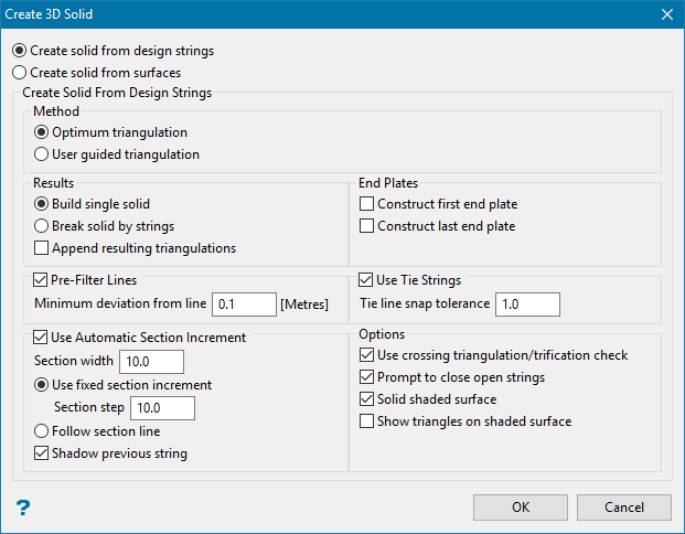
Select one of the two options. The panel options will vary depending on your selection.
 Create solid from design strings - Select this option if you are going to create the solid from a series of strings.
-
Select the Method. This corresponds to the two different algorithms used to triangulate a pair of strings.
-
Optimum triangulation - Automatically calculated links using criterion of proximity.
-
User guided triangulation - Allows you to supply links between points on two strings by using tie-lines.
Note: Both methods try to guess tie-lines if none are given.
-
-
Select either Build single solid or Break solid by strings.
-
Use Build single solid to create a single solid from all the polygons used to create the shape.
-
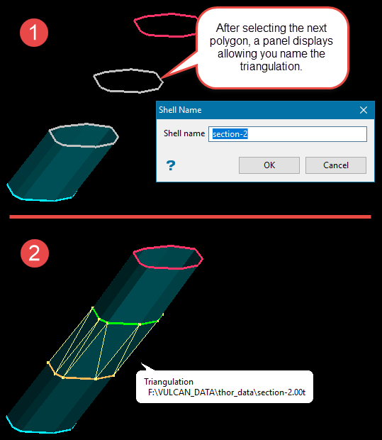
Use Break solid by strings to name the individual sections, breaking at each polygon.
-
-
Enable Append resulting triangulations if you want to create a new triangulation by adding loaded triangulations. The original triangulations are not affected. This option can be used, for example, to create a triangulation of an entire pit from the designed slope surfaces and existing topological structures (for example pavement horizon or surface topography).
-
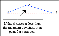
Enable Pre-filter Lines to reduce the number of points on the polylines, thus reducing the processing time for triangulation of those polylines.
If you use this option, you will need to enter the Minimum deviation from line. This is the minimum distance between a point and the line joining the points either side of the point in question. The point will be removed if it is closer to the line than this value.
-
Enable Use Automatic Section Increment to set up a section view, selecting each polygon that you want to use as you step through the section.
If you use this option, you will need to enter the Section width. This is the step distance between each section view. Enter the distance that is moved each step when moving the section through space.
Note: Using section increments does not stop you looking at the data in 3D. However, when you go back to selecting, it will return to the section on which you are working.
-
Select either Use fixed section increment or Follow section line.
-
Use fixed section increment - Navigate through the sections at fixed intervals.
-
Follow section line - Use an polyline as a section guide. The sections will be displayed perpendicular to the first segment of the line.
NoteTo move the section through space, use the Slice Forward
 or Slice Backwards
  icons on the Slice toolbar.
Alternatively, you can also select the Align View With Current Slicing Plane icon
 on the Slice toolbar and use the up and down arrows to move through space.
 -
-
Enable Shadow previous string to render the objects that falls outside the section width as shadowed.
-
Use this option to Construct first/last end plates to close a solid triangulation. You have the option of creating one or both end plates, or none at all.
-
Enable Use Tie strings to allow more control in defining how the shape will be created.
Tie strings must be digitised in the same direction.
If you select Use Tie Strings, then the Select By panel displays. From this box, choose the method of selecting the tie strings and select the tie strings.
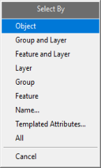
Click the selection criteria on the Select By menu.
NoteYou can exit the Select By menu at any time by right-clicking or clicking Cancel.
Object Click on the object(s) that you want to use to cut the triangulation. When you finish selecting objects, right-click to return to the Select By menu. Group and Layer Click on an object that is part of the group and layer combination that you want to use to cut the triangulation. Click the Group and Layer combination from the Confirm menu that displays, or click Try again to select a different combination. When you are finished selecting combinations, right-click to return to the Select By menu. Feature and Layer Click on an object that is part of the feature and layer combination that you want to use to cut the triangulation. Click the Feature and Layer combination from the Confirm menu that displays, or click Try again to select a different combination. When you are finished selecting combinations, right-click to return to the Select By menu. Layer Click on an object in the layer that you want to use to cut the triangulation. Click the Layer name from the Confirm menu that displays, or click Try again to select a different layer. When you are finished selecting layers, right-click to return to the Select By menu. Group Click on an object in the group that you want to use to cut the triangulation. Click the Group name from the Confirm menu that displays, or click Try again to select a different group. When you are finished selecting groups, right-click to return to the Select By menu. Feature Click on an object that has the feature that you want to use to cut the triangulation. Click the Feature name from the Confirm menu that displays, or click Try again to select a different feature. When you are finished selecting features, right-click to return to the Select By menu. Name Enter any combination of Layer, Group, Feature, and Object names that you want to select. To include all names for a particular attribute, enter an asterisk ( * ) for that attribute. If you want to exclude a layer, group, feature, or object by name, click the Exclude check box next to the name. Click OK to save selections, and then click Cancel to return to the Select By menu. 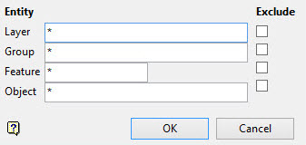
All Click All to select all objects. -
Select any additional options.
-
Use crossing triangulation/trification check - Performs a validation check.
-
Prompt to close open strings - Displays a warning if selected string is not closed.
-
Solid shaded surface - Display completed solid with shaded surface instead of as a wireframe.
-
Show triangles on shaded surface - Superimposes a wireframe on top of shaded surface to make individual facets more visible.
-
-
Click OK to continue, or click Cancel to exit the option.
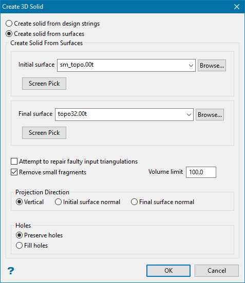
Create solid from surfaces - Select this option if you are going to create the solid from triangulated surfaces.
This option allows you to build solids defined by two surfaces working in plan view. The surfaces are assumed to be two successive topographies. The solids between them correspond to Cut and Fill solids. There is no constraint on surface sizes or mutual position apart from the overlap in plan view.
Tip: For the best result, the surfaces should be consistent and have no crossing triangles.
Follow these steps:
-
Select the Initial and Final surfaces.
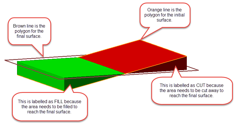
The initial surface is the surface you are starting with, and then filling (or cutting) toward the final surface. The new solid will include all areas between the initial and final triangulations. However, any area that is above the final surface will be labelled as fill, and any area that is below the final surface will be labelled as cut.
-
Enable Attempt to repair faulty input triangulations if the input surfaces have some inconsistencies or have crossing triangle. If the re-triangulation is successful, the result of the re-triangulation is saved with a new name formatted as
<inputFileName>_reTri.00t. The result of the re-triangulation will used to build the solids instead of the corresponding faulty input. If the re-triangulation result cannot be repaired, the original triangulation is used. -
Enable Remove small fragments to remove small sections that are below the threshold volume limit. If you use this option, you will need to enter a Volume limit.
-
Select the Projection Direction based on the three choices.
-
Vertical - The projection will be oriented in plan view.
-
Initial surface normal - The projection will be oriented perpendicular to the initial surface
-
Final surface normal - The projection will be oriented perpendicular to the final surface.
-
-
Select either Preserve holes or Fill holes.
-
Preserve holes - If there are holes in the surface triangulations, then this option will create the new solid keeping the holes.
-
Fill holes - This option will attempt to fill in any holes that are present in the surface triangulations.
-
-
Click OK to continue, or click Cancel to exit the option.
-
-
Select the strings/polygons to triangulate from the screen. You may select either open or closed polygons. Polygons used for the triangulation do not have to be co-planar.
Tip: To achieve accurate 3D models ensure that all strings are in the same direction, or that no duplicate points exist.
Note: Although the strings may be open or closed, open portions of a polygon will not be triangulated.
At any time during the string selection process, you can access the floating Create panel containing picking preferences.
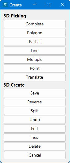
Complete
Select this option to use all of the points on the next selected string to create the triangulation.
Polygon
Select this option to digitise a polygon while building the solid. You will need to assign a layer.
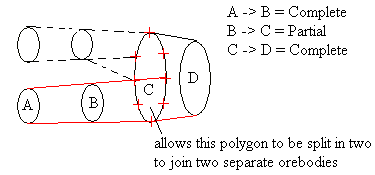
Partial
Select this option to specify the start and end points of a selected string. Thus separating a string into two sections. Once selected, a part of the string will be highlighted and you will need to specify whether or not you want to triangulate this part or the remaining section. This option is useful when triangulating bifurcating ore bodies (sometimes referred to, in 3D modelling, as trouser legs).
Line
Select this option to digitise a line to which you want to join triangles.
Multiple
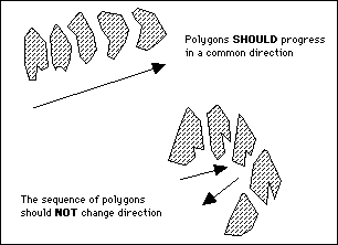
Select this option to triangulate a layer of polygons rather than selecting each polygon for inclusion. The system will determine the order of the polygons in the layer and build the solid in one pass. Checks for crossing triangles are carried out automatically.
This option will only work if the polygons progress in a common direction.
Point
Select this option to select a point to which to triangulate.
Translate
Select this option to copy and translate existing polygons. You will need to specify the layer in which to place the translated polygons.

The Translate Polygon panel will also be displayed.
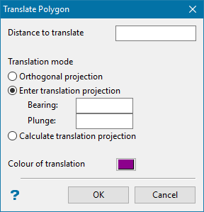
Distance to Translate - Enter, in world co-ordinates, the distance between the selected polygon and the translated (new) polygon.
Orthogonal Projection - Select this option to translate the polygon perpendicular to the plane of the original polygon and away from the previous triangulation.
Enter Translation Projection - Select this option to enter the bearing and plunge of the translation.
Calculate Translation Projection - Select this option to define the translation as the vector joining the centroids of the two previously selected strings.
Colour of Translation - Select the colour of the new polygon.
Save Allows you to save the solid in its current state, then exits the option. Reverse Use this to alter the order in which the facets are generated if the current section has crossing triangles or other issues. If using this option does not fix the issue, you may need to create tie lines to guide facet generations. Split Use this option to create a new triangulation by splitting a triangulation that contains many disjointed sections. For example, two non-intersecting triangulations appended together. Undo Undo the last operation. Edit Opens the 3D sub-panel, then select a string and edit the points.
Ties Opens the Allocate Layer panel, allowing you to select the layer that contains the ties.
Delete Deletes the selected sequence of triangulated strings. Cancel Cancels the operation. A confirmation dialogue will be displayed before closing asking if you are sure you want to cancel. -
Follow the onscreen prompts to connect the strings, or use the options on the floating panel to make edits.
-
Click the Save button on the floating panel when you are finished.

