Footprint
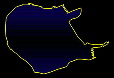
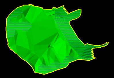
Use the Footprint option to create a boundary polygon along triangulation edges by projecting the triangulation extents to a specific level.
Instructions
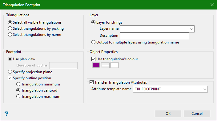
On the Model menu, point to Triangle Utility, and then click Footprint to display the Triangulation Footprint panel.
Triangulations
Choose the method you want to use to select triangulations. Selection is carried out after you OK the Triangulation Footprint panel.
Note: Select triangulations by name enables you to choose a triangulation selection file (.sel). This option can be chosen from the Files of Type drop-down on the Select by name panel.
Layer
Output to single layer
Layer name
Select the layer that will be used to store the registered strings.
The drop-down list contains the names of all layers in the currently open dgd. If you select an existing loaded layer, then the resulting data will be appended to the nominated layer. If you enter the name of an existing layer that is not currently loaded, then you will need to confirm whether you want to load the layer or replace it.
Note: Triangulation names will be used as the object name for resultant polylines.
Description
Enter a description to further describe the contents of this layer. The description can be up to eighty (80) alphanumeric characters and may include spaces. If a description is not entered, then a default description will be used instead. If the chosen layer already has an assigned description, the description displays when the layer is selected. Existing layer descriptions can be overwritten.
Note: Triangulation names will be used as the object name for resultant polylines.
Output to multiple layers using triangulation name
Select this option to use the triangulation name as the layer name.
Note: Using the triangulation name as the layer name will create a separate layer for each triangulation.
Footprint
Use plan view
Select this option to use the plan view as the footprint.
Elevation of Outline is the z value where the polyline result is drawn. The option will draw an outline of a Triangulation in plan view and save it as a polyline. The exception being when Specify outline position is used ( see Specify outline position below ).
Specify projection plane
Select this option to specify an arbitrary plane. Once you OK the Triangulation Footprint panel, the Projection Plane panel will display.
Specify outline position
Select this option to position the polyline results relative to the individual input triangulations. There are three options to choose from: Triangulation minimum, Triangulation centroid, and Triangulation maximum. The exact position of the polyline results depends on the projection plane you choose.
Example: If you choose Specify projection plane and Specify outline position (Triangulation maximum) and then in the Projection Plane panel, you choose Select by grid coordinate, By Easting, the polyline result will be positioned at the maximum easting of the input triangulation.
Below is the Projection Plane panel referenced above.

Important: The Projection Plane panel provides a number of options for specifying both the plane for the resultant footprints, as well as the footprint position in 3D space. You can enter a decimal value in the Coordinate input box to position the footprints. However, the footprint 3D position can also be specified in the Triangulation Footprint panel by selecting Specify outline position and choosing one of the three options. When Specify outline position is selected, only the plan chosen in the Projection Plane panel is honoured, not the 3D position specified in the Coordinate input.
Object Properties
Select the Use triangulation's colour check box to draw an outline of a triangulation in plan view and save it as a polyline.
Note: This option only works for colour pallet colours. It does not work for triangulations coloured with RGB colours.
Transfer Triangulation Attributes
This option allows you to transfer the triangulation attributes from the input triangulation to the templated attributes in the resultant footprint polygons.
You may be regularly required to produce schematic plans showing either labelled blast blocks or, in the case of underground mines, stope longsections. The plans are typically labelled with information such as tonnage and grade.
By transferring attributes already associated with stope or blast triangulation shapes, and assigning those attributes to the resultant polygons produced using the footprint tool, labelling such plans can be done much more quickly by automating the attribute creation process in the polygons.
Attribute template name
Enter a templated attribute name.

