Build Road
Use this option to create road outlines and cut and fill triangulations from a centre line. This option can also apply gradients and curvature adjustments to the centre line.
Note: The Build Road option can also be accessed by selecting the Build Road icon  on the Ramps toolbar.
Instructions
Note: You must have a line already loaded into Envisage as a layer before starting this option.
On the Open Pit menu, point to Ramps, then click Build Road.
Inputs tab
Follow these steps:
-
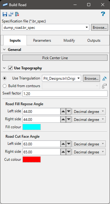
Select a Specification file (*.br_spec) from the drop-down list, or click Browse to select a file from a location other than your current working directory.
-
Click Pick Center Line to select the string representing the centre line of the road.
Note: The string layer must already be loaded onto the screen.
-
Enable Use Topography to use a surface triangulation as the baseline elevation, or to use a layer containing surface contour strings.
-
Select the surface triangulation from the drop-down list, locate it by clicking the Browse button, or select it from the screen by using the screen selection icon
 .
. -
Select the surface contour layer from the drop-down list, locate it by clicking the Browse button, or select it from the screen by using the screen selection icon
 .
.
-
-
Enter the Swell factor. The range of swell factors is limited between 1 and 2 The swell factor is a ratio that quantifies the increase in volume of excavated material compared to its original volume in its natural state due to the creation of voids and air pockets during excavation. Essentially, it's a way to indicate the change in density of the material that is removed from the cut volume (in-situ or bank) versus when that same or other material is trucked in and dumped to fill in the fill volume but it is no longer as compact as it was undisturbed in it's original location.
Example: A swell factor of 1.2 means the material will swell in volume by 20% to take up additional space while the mass is unchanged.
-
Set the Road Fill Repose Angle for both the left side and the right side. You can enter a value directly, or use the buttons to increase or decrease the values.
-
Set the Road Cut Face Angle for both the left side and the right side. You can enter a value directly, or use the buttons to increase or decrease the values.
Values below 15 deg will result in the following validation message, “Shallow in road fill repose may produce inconsistent results.”
Note: For both the fill repose angle and cut face angle, you can customise the units as decimal degree, gradian, or percentage. You can also customise the colour of the resulting triangulations by clicking the Fill colour or Cut colour icons.
Parameters tab
Follow these steps:
-
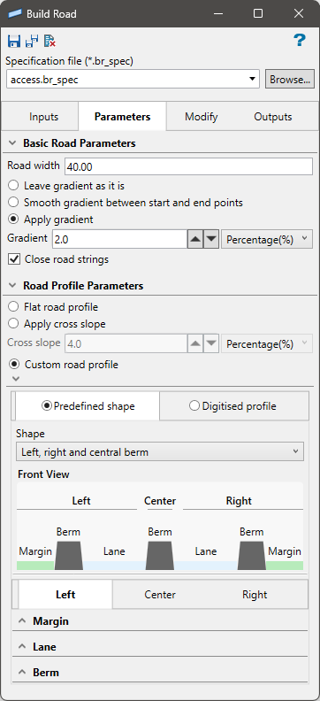
Enter the width of the road into Road width.
The road width will be defined in custom profile when Auto fill remaining width is disabled.
-
Select a gradient option. You have three options:
-
Leave gradient as is - Select this option to leave the centre line unaltered.
-
Smooth gradient between start and end points - Select this option to calculate the gradient of the centre line by using the two end points. The remaining points are then moved to suit this gradient.
-
Apply gradient - Select this option to apply a nominated gradient to the centre line. The gradient is applied to the centre line in the direction of the point sequence. Point one remains at its original location and the remainder of the string is re-graded as specified.
The gradient value can be entered as a percentage, a gradian, or as decimal degrees. To do so, select the appropriate angle format option and enter the value. The format of
<negative value>:<value>must be used when entering negative ratios, For example,-1:7.
-
-
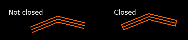
Select Close road strings to close the road strings to create a closed polygon.
-
Choose the Road Profile Parameters by selecting either Flat road, Apply cross slope, or Custom road profile.
-
Flat road profile - Select this option to maintain a flat profile from one side of the road to the other.

-
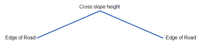
Apply cross slope - This allows you to create a symmetrical profile from the centre of the road to the edges. Increase or decrease the Cross slope value to adjust the gradient of the profile. The gradient value can be entered as a percentage, gradian, or as decimal degrees.
-
Custom road profile - Use this option to create a more complex profile using the tools provided. Select Predefined shape to use simplified tools to adjust the margin, lane, and berm in the road profile. Select Digitised profile to draw a customised profile.
 Predefined shape
-
Select the type of profile you want to create using the Shape drop-down list. A basic diagram defining the location of each parameter (margin, lane, and berm) will display, as shown here. The diagram will change depending on which profile you select.

The profile diagram is for reference only and will not change as edits are made to the parameters.
-
It is possible to edit three separate parameters depending on the selection made in the Shape drop-down list.
-
Margin - enter a value for the width and slope.
-
Lane - Enter a value for width and slope. You can enable the option Auto fill remaining width to allow the Vulcan to automatically calculate the widths of any berms or margins, then assign the remaining width to be attributed to the lane.
Note: The road width will be defined if Auto fill remaining width is disabled.
-
Berm - Enter a value for the height, top width, and base width.
Tip: As edits are made, the road profile will be changed dynamically, allowing you to see the effect of your edits on the screen. Adjust the viewing angle to optimise your view using the Rotation tool.
-
Digitise profile
-
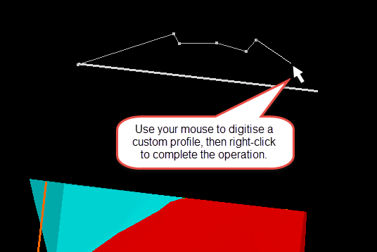
Click Digitise Profile to digitise a new profile on the screen.
A line representing the width of the road will be displayed in plan view near the beginning of your road. Begin by indicating the starting point of the profile. Click as many times as you need to create the shape you want, then complete the operation by right-clicking. The new profile will be applied immediately to the road, allowing you to see the results.
-
Click Show Digitised to display the profile outline after it has been created.
-
Click Hide Digitised to remove the profile outline.
-
Click Pick Profile to use a pre-existing layer as a profile.
Note: The string used in the layer does not need to be the exact width of the road because the length will be automatically scaled to fit the road width.
-
-
Modify tab
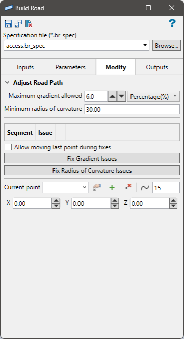
Follow these steps:
-
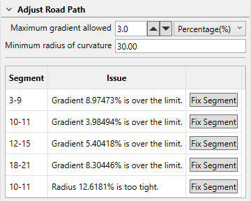
Set the Maximum gradient allowed. Any segment of the road that exceeds this threshold will be flagged as being too steep.
-
Set the Minimum radius of curvature. Any curve along the road that has less of a radius than this threshold will be flagged as being too tight of a curve.
-
Click the Fix Segment button if you want Vulcan to attempt fixing the string automatically in areas where issues have been flagged. Rather than having one button for all flags, Vulcan will separate each flagged problem area and show the reason it was flagged. As each issue is corrected, it will be removed from the list.
-
Enable Allow moving last point during fixes if you want to allow Vulcan to move the last point of the line segment being fixed to be moved during the attempt to fix any issues. If this is not enabled, the point will remain fixed in place.
-
Click the Fix Gradient Issues or Fix Radius of Curve Issues to allow Vulcan to fix all issues at once.
-
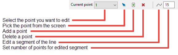
Use the following controls to edit the string making up the road.
Outputs tab
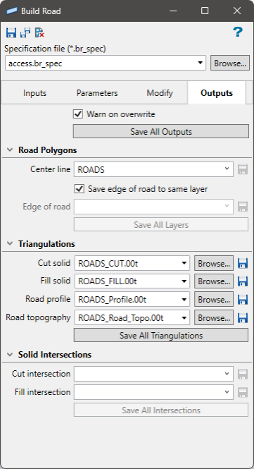
Follow these steps:
-
Provide names for each layer or triangulation that you want to save.
Road Polygons - These are the finished road design strings. They are saved as a single layer (if the option Save edge of road to same layer is enabled), or as a Center line layer and Edge of road layer.
Triangulations - These are all the triangulations that will be generated from the Build Road option.
Solid Intersections - The solid intersections are layers that can be used to designate areas of possible disturbance during road construction, either from cutting or dumping of fill.
-
Click any of the Save buttons to generate output.
Save All Outputs - Generates and saves all the layers and triangulations produced by the Build Road option. Enable Warn on overwrite if you wish to display a message stating that one or more objects will be overwritten due to having the same name as an already existing object.
Save All Layers - Saves the DGD layers used to produce the roads.
Save All Triangulations - Saves the resulting triangulations. These can also be saved individually by clicking the Save icon located next to each item.
Save All Intersections - Saves the layers showing areas of possible disturbance.

