Report Offsets
Report UG development offsets
The Report Offsets option to calculate a set of horizontal and/or vertical offsets. The offset information can be saved to a report file or posted as graphics onto the screen.
The horizontal offsets are calculated along a survey line defined by two stations, at the given intervals between the chainage start and end distances. The vertical offsets are calculated at the two station points only, and are calculated by taking the vertical perpendicular planes at the two station points and intersecting the selected design line segment with these planes. The vertical offsets are the difference in height between the station points and the intersection points.
Instructions
- Select Survey menu
- Select UG Survey submenu
- Select Report Offsets option
The following panel displays.
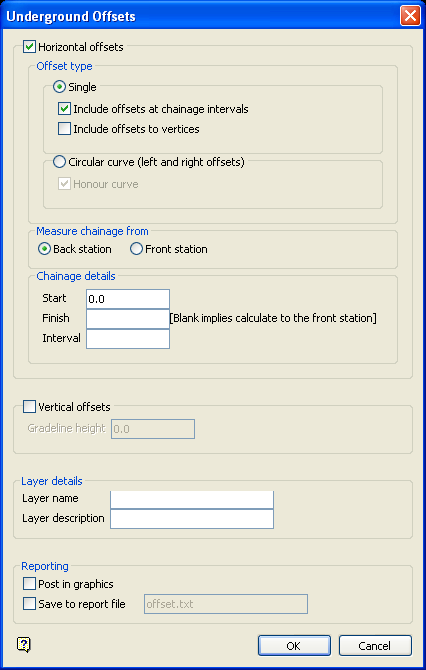
Figure 1: Underground Offsets panel
Horizontal offset
Select this check box to report the horizontal offsets. There are two types of horizontal offsets supported.
Offset type
Select the Single option to calculate offsets perpendicular to a design centre line string. At each interval, the horizontal offset is calculated as the perpendicular distance from the chainage points and/or design vertices to the centre line. The horizontal offsets are reported as positive to the right (looking from the survey stations) and negative to the left.
Check the Include offsets at chainage intervals check box to report offsets calculated perpendicular to chainage points. Check the Include offsets to vertices check box to report offsets calculated perpendicular to design vertices.
Note: If multiple intersections occur, then the intersection point from which the offset distance is the shortest at that interval will be used. If no intersections occur, then the report displays the N/A (not applicable) value for that chainage.
Select the Circular curve option if you want to calculate offsets to the left and right circular curve wall objects. When selecting the curve objects, ensure that your pointer is over one of the segments in the middle of the curve, as the selected segment and its adjacent segments are used to calculate the curve centroid. The calculated offsets are NOT perpendicular to the survey line, but instead projected to the centre of the curve. Two offsets are calculated at each chainage point, that is, the left offsets are to the left string, and the right offsets to the right string. If you check the Honour curve check box, then the offsets are calculated to the exact curves, otherwise, the offsets are calculated to the intersection of the line joining the chainage point and centroid with the respective left and right curve objects.
Note: If the centre curve points of the two strings do not match, then a warning message displays.
Measure from back/front station
All horizon offsets are measured relative to the infinite line that begins at the back station and goes towards the front station. The Measure from the back station option results in the first horizontal offset being calculated at the start chainage distance from the back station in the direction of the front station. The Measure from front station option results in the first horizontal offset being calculated at the start chainage from the front station, but still in a direction that is away from the back station.
Assume that the two stations are 500 metres apart. If you chose to measure from the back station, and set your start chainage distance as 50 metres, then the first chainage point calculated will be 50 metres from the back station and 450 metres from the front station (along the line connecting the two stations).
If you chose to measure from the front station, and set your start chainage distance as 50 metres, then the first chainage point calculated will be 50 metres from the front station and 550 metres from the back station (as the chainage is always measured in a direction that begins at the back station and goes towards the front station).
Chainage details
Start
Enter the starting distance for calculating chainage points, For example, 100.
Finish
Enter the ending distance for calculating chainage points, For example, 1100. If chainage begins at the back station, then this field can be left blank. The offsets will then be calculated up until the front station chainage.
Interval
Enter the chainage interval, For example, 200. The chainage is then set to 100, 300, 500, 700, 900 1100.
Vertical offsets
Select this check box to report the vertical offsets. At each station, the vertical offset is calculated as the difference between the RL of the station, and the RL of the intersection point of the projected design centre line with the vertical section.
Layer name
Select a layer from the drop-down list, or enter a name for a new layer. The name of the new layer:
-
may contain up to 40 characters,
-
must begin with an alphanumeric character [0-9] or [a-z],
-
cannot include spaces,
-
can include hyphens [ - ], plus signs [ + ], underscores [ _ ], periods/dots [. ],
-
can include the special characters of ÁÂÃÀÇÉÊÍÓÔÕÚÜÑ that are used in the Spanish and Portuguese languages.
Layer description
Enter a description to further describe the contents of this layer. The description can be up to 80 alphanumeric characters and may include spaces. If a description is not entered, then a default description will be used instead. If the chosen layer already has an assigned description, the description displays when the layer is selected. Existing layer descriptions can be overwritten.
Reporting
Post in graphics
Select this check box to post the offsets onto the screen.
Save to report file
Select this check box to save the chainage and offsets to a specific file. You will need to specify the name of the report file (a maximum of 20 alphanumeric characters). You can also save the report from in the Report Window.
Select OK.
You will then need to indicate the back survey station, followed by the front survey station. Indicate or one of the Snap modes may be used (see the Digitise toolbar for details on Snap modes).
Select the object for the design centre line.
If you chose to report the vertical offsets, then the centre line will be highlighted and you will need to select a line segment as the projected design centre line in order to calculate the vertical offsets.
If you chose to report the vertical offsets, as well as circular curve horizontal offset, then another string and segment needs to be selected. This is due to the centre line curve generally being used for the vertical offset, while the wall curves are used for the horizontal offsets.
If you choose to report the vertical offsets, as well as single horizontal offset, then the same object is used for both the horizontal and vertical offset calculations.
If you chose to only report the horizontal offsets, then you will only need to select the centre line. If you chose to post the offsets onto the screen, then you will need to indicate the position from which to post. Once indicated, you will be asked whether or not this is the correct position.
The offsets are then calculated and displayed in the Report Window of Vulcan. The offsets, if requested, are also posted onto the screen.
Note: The report file only displays the chainage and offset set-outs Layer names are not included in the report file, but are displayed in the Report Window.

