Open Specification
Use Open Specification to load, maintain the scenarios of, and add a block model to a previously saved stope optimisation (.sof) parameters file.
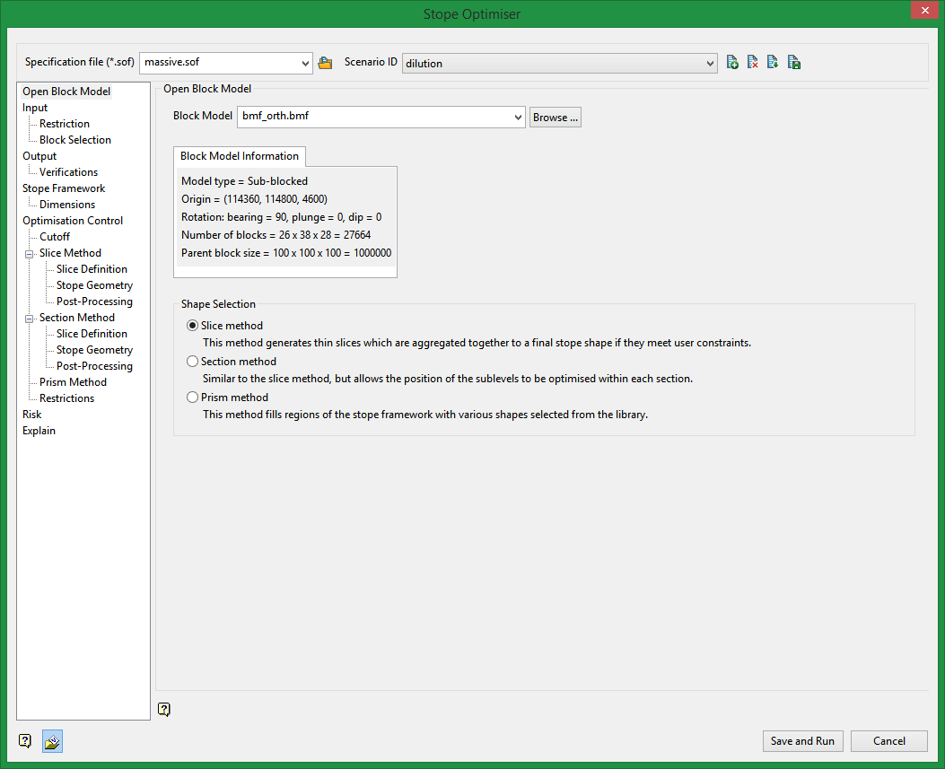
Specification file
Stope optimisation specification file (.sof)
Select the .sof specification file to load. The drop-down list displays all available.sof files found in your current working directory. Click Browse to select a file from another location. The settings and information contained in the .sof specification file will populate various fields in the Stope Optimisation panels.
Scenario ID
A scenario is a set of parameters with the (.sof) file that is used to build one specific (.sml) file. This.sml file is then processed, and optimised stopes are generated. You can choose to select an existing scenario and create optimised stopes, copy an existing scenario and save it to a different name, modifying it as desired, or create a new scenario. The (.xml) file created will be named specification file_<scenario>.xml. For example, a specification file named basic.sof with a scenario of case1 would be named basic_case1.xml.
Block Model
Select the desired block model from the drop-down list. The drop-down list displays all block models found in your current working directory. Click Browse to select a file from another location. Selecting a different block model will reset the Input option settings to their default. Be sure to check the settings in that option before saving and running your project.
Shape Selection
Slice method
The Slice method first generates thin slices, which are then aggregated into stope seed shapes that satisfy stope and pillar width constraints, and an orientation that is defined by a Stope Control Surface, Dynamic Anisotropy fields in the input model, or as a last resort the default dip and strike angle. The Slice Method then anneals the seed shapes to the final stope shape satisfying stope and pillar width and other geometry constraints. The output mining units can have the full dimension of the long section axis ("full stopes"), or partial dimension ("sub-stopes")
Section method
The Section case allows the position of the sub levels to be optimised in each section of the framework extent. Alternatively a section control string can be supplied to control level position in each string.
Prism method
The Prism method allows a combination of shapes to be selected from a library of shapes to fill each region Regions are used to subdivide the problem space as the optimisation problem might otherwise be too big if the entire framework was a single cell. in the regular stope shape frame work definition with an optimal combination of shapes.
Related Topics
Section Method Slice Definition
Section Method Post Processing

