STOPE SHAPE OPTIMISER
Introduction
The Stope Shape Optimiser by AMS (also referred to as "SSO" in this manual) is used to produce stope-shapes and stope inventories from a block model that spatially represents the location of the mineralisation. The SSO algorithms rely on a sub-cell block model to define the spatial location of mineralisation (usually defined from a geological wireframe). The SSO is not applicable for regularised block-models that use a percentage-populated field for contained metal (grade) or value (dollars).
The SSO application mimics what an engineer would do, generating strings on sections, linking these to create a wireframe shape and then evaluating the wireframes against a block model. The SSO provides a stope-shape that maximises recovered resource value above a cut-off while also catering for practical mining parameters such as; minimum and maximum mining width, anticipated wall dilutions, minimum and maximum wall angles, minimum separation distances between parallel and sub-parallel stopes, minimum and maximum stope heights and widths, etc.
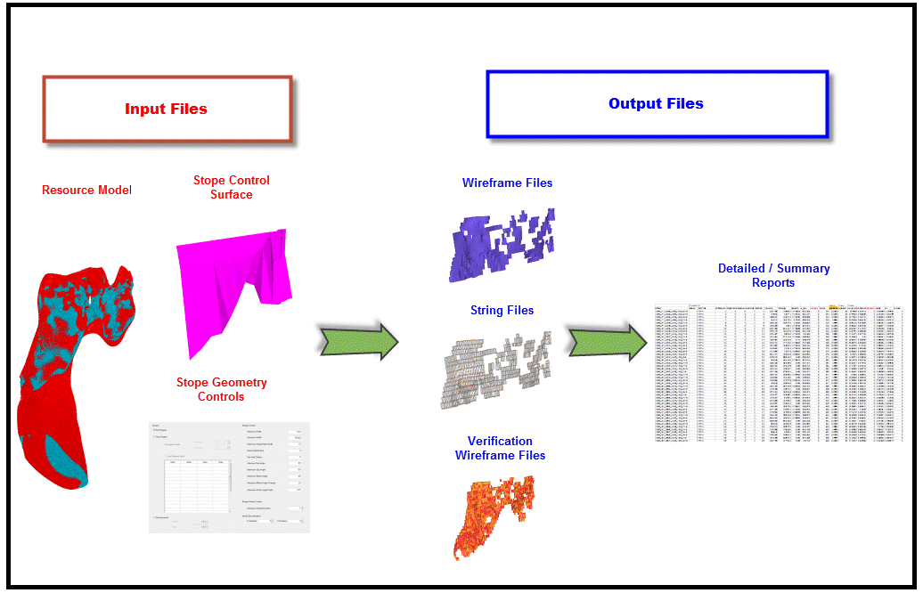
Figure 1-1 summarises the general process flow for the SSO.
Figure1-1 Stope Shape Optimiser Process Flow
This document discusses the Stope Shape Optimiser methods, the typical optimisation applications and clarifies the input parameters for the optimisation methods.
Block Model
The following discusses the general block model requirements and good practice.
The block model must spatially represent the location of the mineralisation. Regularised models that use a percentage populated field are not applicable for SSO. These models however can be converted by over-printing cells filled within the mineralisation wireframe(s) over the regularised model to create a sub-celled model. The cell size and the level of sub-celling used in the block model will determine the precision of the orebody representation.
For mining software vendor packages that use a cell filling plane for populating a block model (i.e. the following is not applicable to say Maptek models), the cell filling plane should ideally be aligned with the strike plane of the orebody such that sub-celling occurs perpendicular to the proposed mining width. For example, if the orebody is tabular and the strike plane is generally YZ then the filling plane should ideally also be YZ so that sub-cells terminate exactly at the orebody X-axis extents. The cell filling orientation has implications regarding the SSO accuracy for optimising and evaluating the stope-shapes.
Models should ideally have an enclosing envelope of waste cells modelled around the mineralisation. The surrounding waste is required for cases where a sub-stope may be mined adjacent to a full stope using waste pillar criteria (a SSO function requirement). If sub-stopes are not required, then unmineralised waste cells can be filtered from the block model to reduce run times.
Models should ideally avoid absent data (for example ’-‘in CAE Studio models), especially for the density field, the cut-off evaluation field or any other reported field(s). For the situation where cells have “absent” values or where cells are missing from within the stope-shape, the default value supplied for each field is applied. Careful consideration is required regarding the default values selected, especially regarding the optimisation field. For example if the optimisation field is a metal grade field then zero may be appropriate, but if the optimisation field is a value field (e.g. net smelter return dollar value) then a negative number representing the cost to mine (and process) waste may be more appropriate than a zero value.
The block model cell size should ideally correlate with the definition of the mineralised zone such that several cells define the stope width (XZ/YZ strike orientation) or stope height (XY/YX plan orientation). One or two cells representing the stope width/height would generally be too coarse to represent the ore-body grade distribution.
The model must have definitions for the size and number of cells, origin and optional rotation (if applicable) and be able to be expressed with the CAE Studio model definition conventions. The model definitions used internally by the SSO are the set of fields [IJK, XC, YC, ZC, XINC, YINC, ZINC, NX, NY, NZ, XMORIG, YMORIG, and ZMORIG]. For rotated models, the optional rotation fields [X0, Y0, Z0, ANGLE1, ANGLE2, ANGLE3, ROTAXIS1, ROTAXIS2, and ROTAXIS3] are also used internally by the SSO. The rotation point [X0, Y0, Z0] used is at the origin of the model. If a Maptek Vulcan model is supplied, the SSO rotation point is recalculated from the Maptek Vulcan rotation point and offset distance.
Stope Optimisation Overview
There are two mutually-exclusive optimising methods available within the Version 2 optimiser engine. These are;
-
Slice Method and,
-
Prism Method.
These methods are briefly explained here, and described in more detail below.
Stope-shape frameworks generally prescribe the orientation and three-dimensional constraints for determining stope-shapes, their allowable dimensions and the manner in which they are optimised.
The stope-shape frameworks are initially categorised by the optimisation technique used, being:
-
Slice. This method optimises strike by height/width projections of stope shapes in the transverse orebody direction (width/thickness), depending on its orientation (vertical or horizontal).
-
Prism. This method optimally combines a set of shapes from a library of stope-volumes within regions without allowing overlapping of the generated stopes.
Slice Method
The Slice Method is typically applicable to narrow to wide tabular-like ore bodies that may be sub-vertical to sub-horizontal dipping and is also well suited to multiple parallel to sub-parallel ore lenses and/or splays. (See Figure 1-2)
The Slice Method generates and evaluates thin slices across the mineralised zones that are aggregated into seed-shapes (looking at all possible permutations) that satisfy stope and pillar width constraints. The seed-shapes are then annealed to the final optimised stope-shape satisfying the stope and pillar width, stope geometry constraints (e.g. wall dips angles, strike twist, etc.), and other miscellaneous constraints (e.g. zone mixing, exclusion zones, etc.). The result is a set of stope-shapes constrained to the basic limitations of the Vulcand mining method.
Seed-shape Generation and Stope-shape Annealing
The following overview discussion is limited to the Slice Method.
At a high-level there are four stages in the SSO process that are described as follows:
1) Seed-slice: Analogous to sample intervals across the mineralisation in the transverse direction.
2)Seed-shape: An aggregation of the seed slices into seed-shapes that satisfy stope and pillar width constraints and cut-off, and other miscellaneous constraints. The role of seed-shape generation is to correctly identify the number and approximate location of stopes, with emphasis on predicting the correct number.
3)Stope-shape: Seed-shapes that are annealed to form the optimised stope-shape inclusive of internal dilution to form a practical stope-shape. Seed-shapes may be discarded if they fail stope geometry or other stope criteria. In rare cases the annealing process may eliminate a seed-shape to expand an adjacent seed-shape.
4)Diluted stope-shape: (inclusive of wall skin dilution(s)). As annealing is applied to the undiluted stope-shape, the addition of dilution may cause the stope-shapes to be discarded at this stage if the skin dilution drops the head grade below cut-off. These marginally sub-economic stopes can also be output for review.
The SSO process generates thin slices (seed-slices) across the mineralised zones that are aggregated into seed-shapes that satisfy stope and pillar width constraints and cut-off. The SSO looks at ALL possible combinations of seed-slices and selects the aggregated seed-slices that yield the highest value above cut-off. SSO operates quite differently to how many users anticipate a typical algorithm might work. A typical heuristic could be to identify grade intervals, retain them if they meet the minimum interval length, and then merge to carry short intervals with other acceptable length intervals. These interval heuristics and similar strategies are not used by SSO as they fail on a number of grounds: - they are not guaranteed to yield the optimal solution, and cannot deal with more complex situations with multiple lenses and variable grade distributions; or specific end-cases where it might be optimal to have waste added to ore, or pillars containing ore; to meet the stope and pillar width parameters.
The seed-slices or aggregates of seed-slices are only added to the seed-shape(s) if the cumulative value of the slice aggregate falls above the cut-off. The only exception would be where the stope geometry or other miscellaneous constraints also had to be satisfied. The grade or value for the aggregated slice-volumes above and below cut-off must be equal-to or greater-than the nominated cut-off to allow inclusion to the stope-shape. The cut-off concept is described in more detail under 4 OPTIMISATION OPTIONS (SLICE & PRISM), under Cut-off and Head Grade.
The seed-shapes are annealed to form the optimised stope-shape (prior to the addition of wall skin dilution(s)), that is inclusive of internal dilution to form a practical stope-shape based on the geometry parameters applied. The final stope-shape wireframe includes the dilution skin(s) - if applicable.
Stope-shape annealing adjusts the stope corners in an iterative fashion to progressively improve the stope value from that obtained at the seed-shape generation stage. The stope-shape wireframe is evaluated against the block model for each adjustment. To generate the final stope-shape, thousands of adjustments might be tested. The overall time taken depends largely on the stope wireframe evaluation procedure, which can be relatively slow. Consequently, the better the initial seed-shape approximates the final stope-shape, the fewer annealing iterations will be required, and the optimiser will complete sooner.
The seed-slices, seed-shapes, and stope-shapes can all be exported to an optional “verification-wireframe” file, described in more detail under 2 SLICE METHOD - Wireframe Types.
Seed-Slice Orientation and Seed-Slice Interval
The seed-slice orientations can be defined by using one of (in increasing order of utility):
a) Default “dip and strike angle” settings (least preferred option).
b) Using “Dynamic Anisotropy” fields contained within the input block model. "Dynamic Anisotropy" is a specialised interpolation technique that generates a local strike and dip at each cell centre from the orientation of bounding geological wireframes. It is typically used to deal with anisotropy in folded orebodies and has some minor advantages over the "Stope Control Surface", but has the possible disadvantage of being dependant on the model cell size.
c) A “Stope Control Surface” which is a simple wireframe to define the general orientation expected for the stope-shapes in the mineralised zones of the orebody. This is the most preferred option as it is customised to the specific requirements of SSO, is quite efficient, and is independent of model cell size.
If the Stope Control Surface or Dynamic Anisotropy field data does not extend to all areas, then the default dip and strike angle settings will be applied in the undefined areas.
The seed-slice orientation and seed-slice interval are key parameters for the successful generation of the seed-shape. A seed-shape cannot be formed without seed-slice(s) above cut-off. A stope-shape cannot be generated without a seed-shape.
While a geology wireframe is often a good proxy for the stope orientation, the geology wireframe is often far too detailed for the purposes of stope generation. Blindly using the geology wireframe can sometimes lead to unexpected results or missing stopes that arise from kinks and inflections in the geology wireframe surface.
In most cases, and in particular for narrow orebodies, a Stope-Control-Surface (i.e. a surface representing the expected orientation of the stope-shapes) is the preferred method for defining the seed-slice orientation. A complex surface is not required (and generally no more than a few thousand triangles are usually needed even for irregular orebodies). Digitising cross-section view strings that represent the general dip trend of the orebody (and hence the general dip trend of the stope-shapes) and forming simple wireframe surface from these strings is usually sufficient. Alternatively, decimating the geology surface (i.e. reducing the number of triangles and hence smoothing) by typically 80% may achieve a similar simplified surface representing the intended dip trend of the stope-shapes.
The seed-slice interval should ideally be a sub-multiple of the minimum stope width, the dilution widths on both sides of the stope-shape (near/far or hanging wall/footwall) and half of the minimum pillar width. This requirement at the seed-slice generation stage becomes more important if there are many lenses that will form narrow stope-shapes with a minimum pillar width between lodes. As a general rule, a seed-slice interval that generates a minimum of 3-5 seed-slices for the minimum stope width is recommended. Typically generating more will increase the run time for little benefit, and conversely, generating less will reduce the result quality.
Prism Method
The Prism Method is typically applicable to massive orebodies or wide/thick deposits whose stopes tend to be designed by blocking out the orebody in a grid-like pattern.
The Prism Method allows the user to define a library of possible stope-volumes by using permutations of stope length, width and height (as rectangular prisms). The library of stope-volumes can be defined as rectangular-prisms or defined as prisms with a centralised undercut-trough (i.e. a shape like an inverted “milk-carton”). The stope-library can be developed quickly by using minimum, maximum and step increments for each axis or the library can be explicitly defined giving specific axis dimensions for each stope-volume.
The Prism Method optimally combines the stope-volumes within each framework region with no overlapping of either regular or various irregular stope-volumes (i.e. it selects the optimum non-overlapping combination of rectangular stope-volumes). The goal of the optimisation is to select the set of non-overlapping stope-shapes that maximises value for the material to be extracted by the selected stope-shapes. All possible combinations of shapes and positions are considered in the optimisation.
As an example, a typical goal of optimally combining stope-volumes with different dimensions (e.g. a small footprint stope adjacent to a large footprint stope) is to determine the optimal orebody footprint.
Optimisation Methods – Relationship to Mining Methods
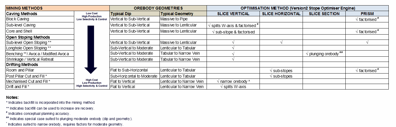
Figure1-2 summarises the various orebody classifications (geometry and dip) that are used inTable1.1to describe a range of mining methods and the corresponding Stope Shape Optimiser method that is most applicable to that mining method. In certain cases, some of the Stope Shape Optimiser method(s) could potentially be used for high-level assessment (+/-30 to 50%) by applying modifying factors. These are noted where applicable in the table.
Figure 1-2 Orebody Classifications
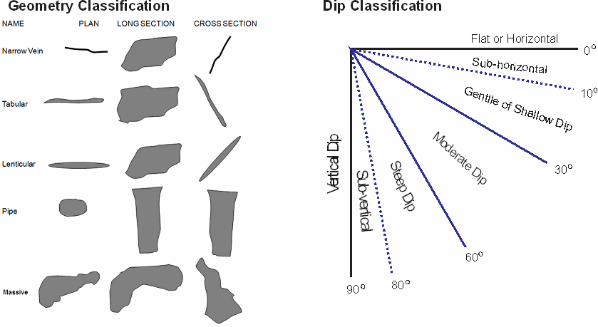
Table 1.1 Stope Shape Optimiser Method Applicable to Various Orebody Geometries and Mining Methods