New
Creating a new design database
Use the New option to create a new design database. These files contain all of the design information relating to a project, such as coordinate points, lines, polygons, features and text annotations.
As only one design database can be open at a time, any open design file will be closed and the new file will be opened. Open design databases have the lock button  displayed to the left of them in the Vulcan Explorer (under the Design Databases ).
It is also possible to create design databases by using the New button ![]() on the Standard toolbar, or by using the File > Design Files > Open option.
on the Standard toolbar, or by using the File > Design Files > Open option.
|
Icon |
Tooltip |
Description |
|---|---|---|
|
|
New |
Allows you to create a new design database. Refer to the File > New option for more information. |
|
|
Open |
Allows you to open files. Refer to the Open option for more information. |
|
|
List Databases |
If you click and hold down the mouse button, then the Open toolbar displays. From this toolbar, you can list Refer to the File > Design Files > List Files option for information on design databases, the File > Layers > List option for information on layers and the File > Open option for information on triangulations, grid models and block models. |
|
|
Remove Layer |
Allows you to remove any loaded layers from the screen. Refer to the File > Layers > Remove option for more information. |
|
|
Remove Underlay |
Allows you to remove data that is loaded as an underlay. Refer to the File > Underlays > Remove option for more information. |
|
|
Remove All Underlays |
Allows you to remove data that is loaded as an underlay. Unlike the Refer to the File > Underlays > Remove All Underlays option for more information. |
|
|
Undo |
Allows you to reverse the last action. Refer to the Design > Undo option for more information. |
|
|
Redo |
Allows you to reverse last Undo action. Refer to the Design > Redo option for more information. |
|
|
Save |
Allows you to save the open design file. Refer to the File > Save option for more information. |
|
|
|
Allows you to create a plot of all of the currently loaded objects. Refer to the File > Plot > Plot All option for more information. |
|
|
Create Section |
Allows you to create a cross-sectional 3D view with a specified dip and width of view. Refer to the View > Create Section option for more information. |
|
|
Delete Section View |
Allows you to delete a section. Refer to the View > Delete Section option for more information. |
|
|
Help |
Launches the Vulcan online help. Refer to the Using Vulcan Help section for more information. |
Instructions
On the File menu, click New to display the Open Design File panel.
If you have made any changes to the currently open design database, you will be prompted to Save or Discard the edits first.
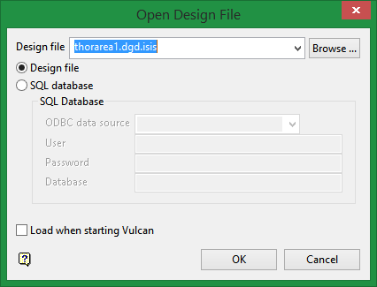
Design File
To create a new design database, enter the spatial database identifier (sdi) without spaces and without the.dgd.isis file extension. The project code will be automatically added to the resulting file.
Example: If the project code is'ABC', and thesdi is'DESIGN', then you only need to enter 'DESIGN to create 'ABCDESIGN.dgd.isis. Remember, no spaces may be used when creating this database name.
By default, the resulting file will be stored in the current working directory. Use the Browse button to select a different file location.
Design File
Select this option to create a standard Vulcan design database.
SQL database
Select this option to connect to an external design database. When using the SQL database option you will need to specify the ODBC data source, the appropriate user name and password as well as the database that will be used to store the actual data.
Load when starting VULCAN
Select this check box if you want the nominated design file to be loaded whenever you start a new Vulcan session. You can specify that Vulcan should start with this design database at a later date by editing the project file.
Click OK.
The database will be created and opened. Before creating any design data it will be necessary to create layers. Layers can be created through using the Design > Create > Layer option or by selecting the New Layer button ![]() from the Design toolbar.
from the Design toolbar.
|
Icon |
Tooltip |
Description |
|---|---|---|
|
|
New Layer |
Creates a new design layer. Refer to the Design > Create > Layer option for more information. |
|
|
Point |
Creates discrete points. Refer to the Design > Create > Point option for more information. |
|
|
Line |
Creates a line consisting of a string of points. Refer to the Design > Create > Line option for more information. |
|
|
Polygon |
Creates a polygon, i.e. a string of points that is automatically closed when the last point is digitised. Refer to the Design > Create > Polygon option for more information. |
|
|
Textured Polygon |
Creates a polygon with a triangulation or textured image tiled over it. Refer to the Design > Create > Polygon Textured option for more information. |
|
|
Rectangle |
Creates a rectangle. Refer to the Design > Create > Rectangle option for more information. |
|
|
Spline |
Creates a line with a 3D Bicubic spline. Refer to the Design > Create > Spline option for more information. |
|
|
Arc |
Creates a circle, arc or spiral. Refer to the Design > Create > Arc option for more information. |
|
|
Ellipse |
Creates an ellipse. Refer to the Design > Create > Ellipse option for more information. |
|
|
Grid |
Creates a 2D grid of points by indicating the grid origin point, two axes and the point spacing. Refer to the Design > Create > Grid option for more information. |
|
|
2D Arrow |
Creates a two-dimensional arrow. Refer to the Design > Create > Arrow 2D option for more information. |
|
|
3D Arrow |
Creates a three-dimensional arrow. Refer to the Design > Create > Arrow 3D option for more information. |
|
|
2D Text |
Creates 2D text. Refer to the Design > Create > Text > Create 2D option for more information. |
|
|
3D Text |
Creates 3D text. Refer to the Design > Create > Text > Create 3D option for more information. |
|
|
Feature |
Creates a feature object. Refer to the Design > Create > Feature option for more information. |
|
|
Symbol |
Inserts a symbol into the current layer. Refer to the Design > Create > Symbol option for more information. |

