New Traverse
The New Traverse option to calculate and check the location of a foresight station by using the position of two know stations. This option, although similar to the Traverse option, incorporates greater functionality; errors are flagged on entry, you can use horizontal distance/vertical distance instead of vertical angle/slope distance, and you can enter radiation data.
Instructions
On the Survey menu, point to UG Survey, then click New Traverse.
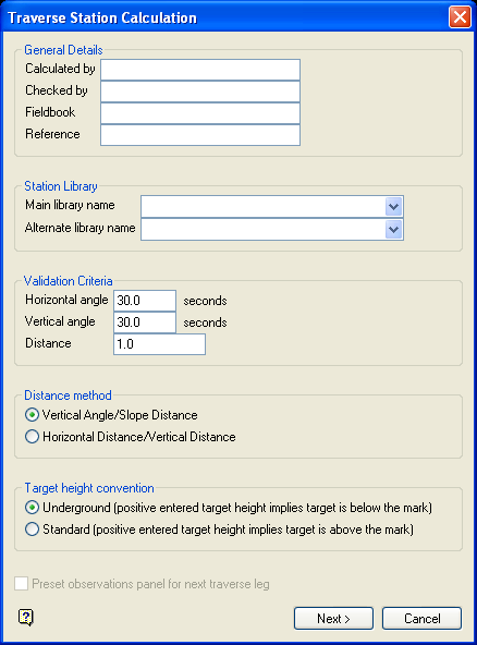
Figure 1: Traverse Station Calculation panel
General Details
The following fields are optional alphanumeric fields of 20 characters.
Calculated by
Enter the name of the person that performs the calculation. The default value is 'Vulcan'.
Checked by
Enter the name of the person that checks the calculation. The default value is 'Vulcan'.
Fieldbook
Enter the name of the fieldbook.
Reference
Enter a job identifier.
Station Library
Main library name
Enter, or select from the drop-down list, the name of the station library that contains the information of the instrument and backsight stations.
Alternate library name
Enter, or select from the drop-down list, the name of an alternative station library that may have been used to store the information of the instrument and backsight stations.
Validation criteria
Horizontal angle
Enter the validation horizontal angle. If you have multiple readings, then the system will check that the difference between the horizontal face left angle and horizontal face right angle is not greater than the given angle.
Note: The angular units format for the value is also displayed. Refer to the Miscellaneous section of the Tools > Preferences option for information on specifying the format of angular units.
Vertical angle
As above, but for the vertical angle.
Distance
Enter the validation slope distance. If you have multiple readings, then the system will check that slope distance one and slope distance two are in this specified value.
Note: If the criteria for any of these sections are not met, then the first column in the report for that particular set of readings is marked with an asterisk.
Distance method
A survey instrument measures the slope distance and a vertical angle. These values allow you to calculate the horizontal and vertical components. Some instruments store the slope and vertical angle, while others store the horizontal and vertical distances. Select one of horizontal distance/vertical distance or vertical angle/slope distance depending on the type of information that your instrument stores.
Target height convention
The target height can be entered using either the standard manner, where a positive number implies that the target is above the mark, or the underground convention, where a positive number implies that the target is below the mark, that is, the distance below the backs to the bob is entered as a positive value.
Preset observations panel for next leg
This option is only applicable when you have completed a traverse leg previously in this Vulcan session
Select this check box to preset the next panel as if you are continuing on with the next leg of the traverse. This will fill in the instrument station and backsight station, and if you entered a reverse survey for the previous traverse leg, then it will fill in the backsight check details and instrument height. If this check box is not checked, then the previously entered data will be used on the panel.
Select Next.
The following panel is then displayed.
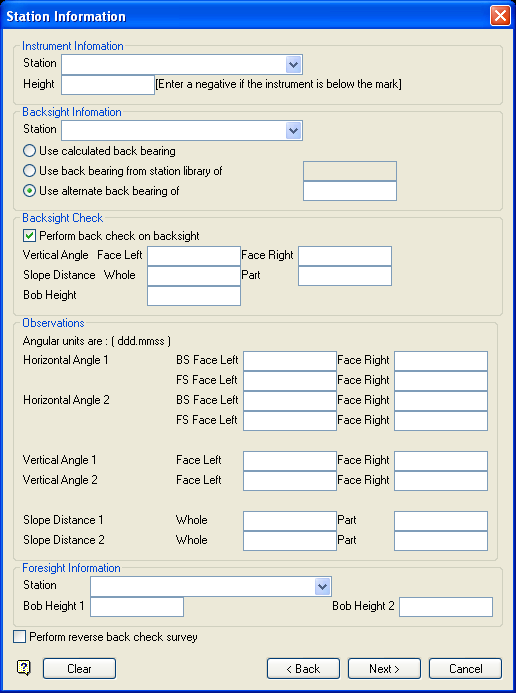
Figure 2: Station Information panel
Instrument Information
Station
Enter, or select from the drop-down list, the name of the instrument station that is stored in the station library or temporary station library specified on the previous panel.
Height
Enter the instrument height.
Backsight Information
Station
Enter, or select from the drop-down list, the name of the backsight station that is stored in the station library or temporary station library specified on the previous panel.
Use Calculated back bearing
Select this option if you want Vulcan to determine the back bearing from the coordinates of the instrument and backsight station (taken from the station library).
Use back bearing from station library of
Select this option to use the back bearing stored in the station library. The field will only contain a value if the current instrument station was originally traversed to from the backsight station.
Alternatively, you can use the Use alternate back bearing option to enter the back bearing.
Use alternate back bearing
Select this option to enter, in ddd.mmss format, the back bearing.
Note: If the instrument or backsight station does not exist in either library, then upon completion of the current panel the Manual Station Entry panel displays.
Backsight Check
Perform back check on backsight
Select this check box to perform a back check on the backsight.
Vertical angle
Enter the vertical angles (Face Left and Face Right) from the backsight instrument to the current instrument. If the angular unit is degrees, then the angle must be entered in ddd.mmss.
Slope Distance
Enter the whole and part of the slope distance. The final distance is the difference between the two.
Bob Height
Enter the backsight instrument bob height.
Observations
This section of the panel displays different fields depending upon the Distance method you selected on the first panel.
Two sets of observations may be entered. The calculation uses the average of both sets.
Note: The angular units format is also displayed. Refer to the Miscellaneous section of the Tools > Preferences option for more information on specifying the format of angular units.
Horizontal Angle
Enter the facing left and facing right horizontal angles for the foresight (FS) and backsight (BS) stations. If the angular unit is degrees, then the angle must be entered in ddd.mmss.
Vertical Angle
This option is only applicable when using the vertical angle/slope distance method. Enter the facing left and facing right vertical angles for the foresight station. If the angular unit is degrees, then the angle must be entered in ddd.mmss.
Slope Distance
This option is only applicable when using the vertical angle/slope distance method
Enter the whole and part of the slope distance. The final distance is the difference between the two.
Horizontal Distance
This option is only applicable when using the horizontal distance/vertical distance method
Enter the horizontal component of the slope distance.
Vertical Distance
This option is only applicable when using the horizontal distance/vertical distance method
Enter the vertical component of the slope distance.
Foresight Information
Station
Enter, or select from the drop-down list, the name of the foresight station.
Bob Height
Enter the foresight target height. If you enter two bob heights, then you must have also enter a second set of observations for this target.
Perform reverse back check survey
Select this check box to perform a reverse back check survey.
If you have specified one bob height measurement and two sets of vertical angle and slope distance observations, then the vertical angles and slope distances are averaged, resulting in one calculated horizontal and vertical distance. This is then used to calculate the new station coordinates.
In any other case, including having two bob height measurements and/or using horizontal and vertical distance observations, the averages of both the horizontal distance and vertical distance values are used to calculate the new station coordinates.
Use the Clear button to remove all of the entries if you want to start again.
Select Next.
If you checked the Perform reverse back check survey check box, then the following panel displays. Otherwise, the Traverse Station Validation panel displays.
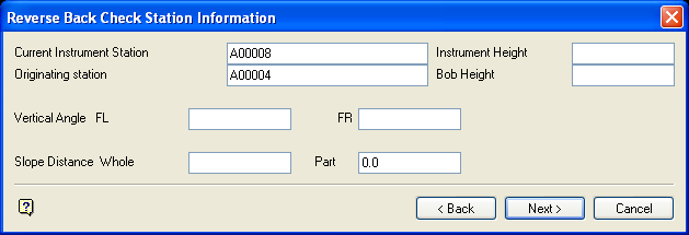
Figure 3: Reverse Back Check Station Information panel
Current Instrument Station
Enter the name of the current instrument station. This station was the foresight station in the previous panel.
Note: The name will usually be entered for you by Vulcan.
Instrument Height
Enter the instrument height.
Originating station
Enter the name of the backsight station. This station was the current station in the previous panel.
Note: The name will usually be entered for you by Vulcan.
Bob Height
Enter the instrument bob height.
Vertical Angle
Enter the face left and face right vertical angles from the backsight station to the current station. If the angular unit is degrees, then the angle must be entered in ddd.mmss.
Slope Distance
Enter the whole and part of the slope distance between the current station and the back station. The final distance is the difference between the two.
Select Next.
The following panel displays.
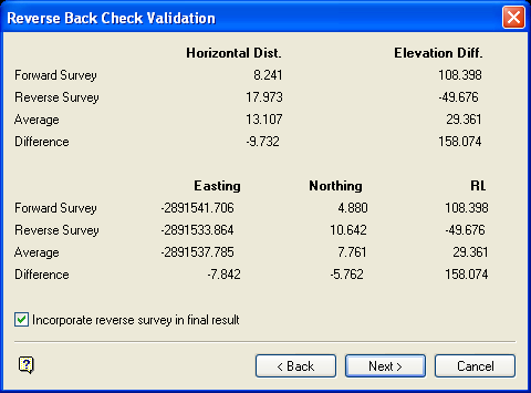
Figure 4: Reverse Back Check Validation panel
This panel shows the results of the reverse back check. That is, the horizontal distance, elevation difference, Easting, Northing and RL of the forward and reverse survey, as well as the average and the difference of all of these values. Check the Incorporate reverse survey in final result check box to incorporate the reverse survey in the final report.
Select Next to continue, or Cancel to return to the Station Information panel.
The Traverse Station Validation Report (see Diagram 4) displays. The details are displayed for ease of verifying. The calculations that have failed the traverse validation criteria are flagged with an asterisk (*) in the first column of the report. If any errors need to be corrected, then use the Back button to go back to previous data entry panels.
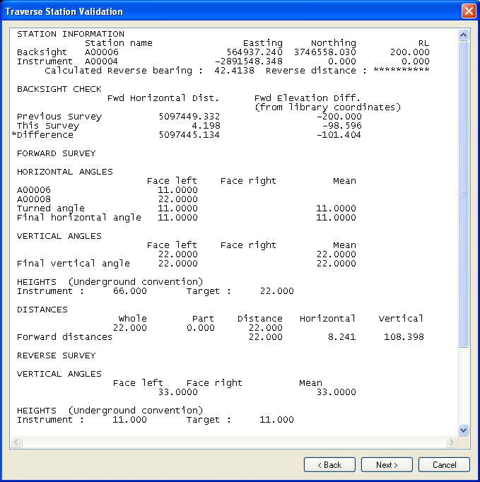
Figure 5: Traverse Station Validation
The following panel is then displayed.
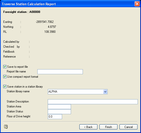
Figure 6: Traverse Station Calculation Report panel
If stations are not found, then the Manual Station Entry panel displays. This to enter the stations manually.
If a station with the same name already exists, then you will be prompted as to whether or not you want to overwrite the contents of the existing station.
The station name, together with its location, are displayed at the top of the panel. The Calculated by, Checked by, Fieldbook and Reference fields are carried forward from the Traverse Station Calculation panel. These details are for information purposes only and cannot be changed on this panel.
Save to report file
Select this check box to save the resulting calculations report to a specific file. The maximum size of the file name, including the file extension, is 20 alphanumeric characters. The .txt extension will automatically be appended to the report file name.
Alternatively, you can also use the ![]() button to save the report from in the Vulcan Report Window.
button to save the report from in the Vulcan Report Window.
Check the Use compact report format check box if you want to reduce the layout size of the calculation report. Refer to the following diagrams for an example of each report format.
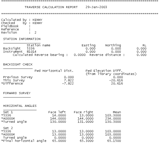
Figure 7: Standard Report Format
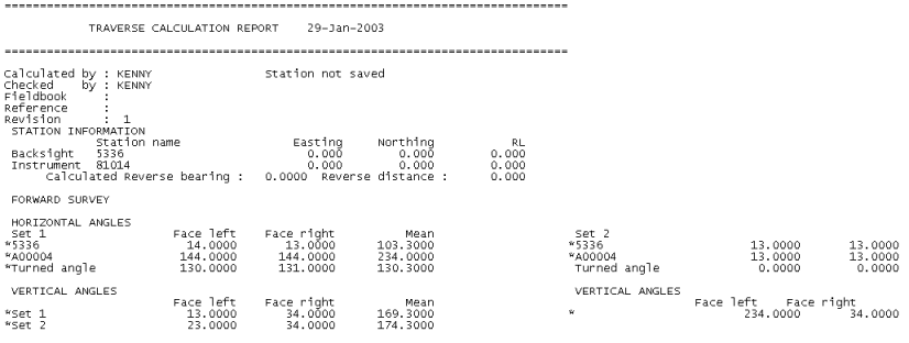
Figure 8: Compact Report Format
Save station in a station library
Select this check box to save the calculated foresight station. If this check box is not checked, then the calculated station will not be saved.
The following options are available when saving the calculated foresight station:
Station library name
Enter, or select from the drop-down list, the survey library into which the station will be stored.
Station Description
Enter a description for the station (maximum 40 alphanumeric characters).
Station Area
Enter the area of the pit or the level where the station is located.
Station Status
Enter the station's status, For example, the accuracy of the station.
Select Finish.
The following panel is then displayed.
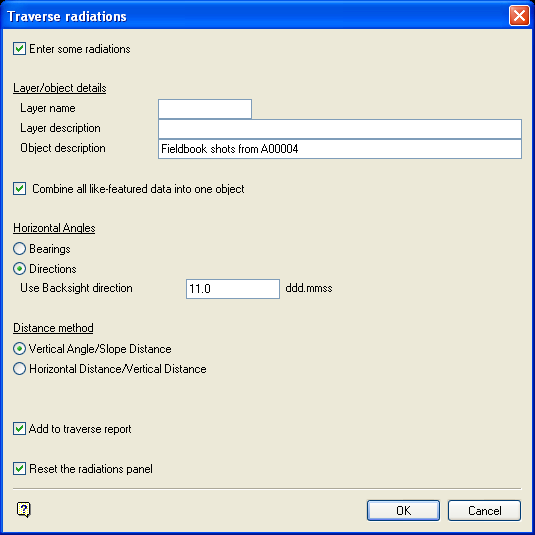
Figure 9: Traverse radiations panel
This panel to specify the name of the shots and the layer in which they are to be stored. These shots are picked up while you were traversing. The panel is optional, so if you don't require radiations, then select OK.
Enter some radiations
Select this check box to enter radiation information.
Layer/object naming
Enter the name (and optionally a description) of the layer in which the shots are to be stored and the name (and description) for each shot, that is, object name. The default object name is <instrument_station>. The default object description is 'Fieldbook shots from <instrument_station>.
Horizontal Angles
The angles can be true bearings or, more often, a direction based on the Face Left/Face right mean to the backsight for the first set of angles (taken from the Traverse panel). Directions is the default.
Distance method
A survey instrument measures the slope distance and a vertical angle. These values allow you to calculate the horizontal and vertical components. Some instruments store the slope and vertical angle, while others store the horizontal and vertical distances. Select one of horizontal distance/vertical distance or vertical angle/slope distance depending on the type of information that your instrument stores.
Radiation Reporting
Add to traverse report
Select this check box to add the radiations to the traverse calculation report.
Select OK.
If the Enter some radiations check box was checked, then the following panel displays. Otherwise the report displays in the Report Window.
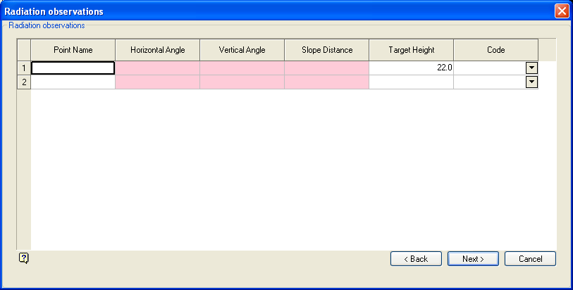
Figure 10: Radiation observations panel
This panel to specify the vertical angle/slope distance or horizontal distance/vertical distance (depending on your entry at the Traverse Station Calculation panel).
Point Name
An optional field of 40 alphanumeric characters.
Horizontal Angle/Vertical Angle/Slope Distance
Enter your measurements.
Target Height
Specify the first target height (this height is mandatory). The default is the height used for the traverse. Subsequent target heights need only be specified if the height changes. Blank target heights assume that the height has not changed.
Select Next.
The radiations are then displayed. You will then be asked whether or not the radiations are correct. If they are correct, then the report is displayed including the radiation information. If the radiations are incorrect, then you are returned to the Traverse radiations panel.

