Build 3D Drive
This option allows you to create 3D drive triangulations from completed development survey data. It uses input strings that define the floor (sill), roof (back) and wall (rib) surfaces. It will also generate polygons at the intersections of the roof and wall, and at the floor and wall.
Refer to the Troubleshooting Guide if you encounter any problems when using the this option.
Instructions
On the Survey menu, point to UG Survey, then click Build 3D Drive.
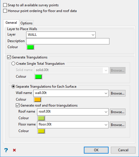
The panel has two tabs, a General tab to input the names of the resulting layer and triangulations, and an Options tab dedicated to designing the shape of the drive.
Follow these steps:
-
Starting on the General tab, decide whether or not you want to use either of the two options at the top of the panel.
Click Snap to all available survey points if you are using a point layer that holds survey point data and you want the resulting solid to create a vertex at every point. You can still use a point layer to guide the resulting shape if you do not use this option, but it will not snap to all the points in areas where the density of points is high or the difference in elevation between points that are closely spaced is extreme.
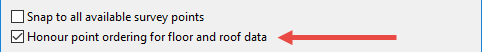
Click Honour point ordering for floor and roof data if you need to add additional points to certain areas to help guide the creation of the solid.
Note: This must be enabled if you want to create an arched tunnel solid by using the input parameters found on the Options tab.
-
Next, enter a name for the layer that will hold the wall polygon strings in the textbox labelled Layer.
The name of the new layer...
-
may contain up to 40 characters,
-
must begin with an alphanumeric character [0-9] or [a-z],
-
cannot include spaces,
-
can include hyphens [ - ], plus signs [ + ], underscores [ _ ], periods/dots [. ],
-
can include the special characters of ÁÂÃÀÇÉÊÍÓÔÕÚÜÑ that are used in the Spanish and Portuguese languages.
Note: We recommend that you use the survey job name as the layer name.
You can also add an optional Description as well. The description can be up to 80 alphanumeric characters and may include spaces.
-
-
If you wish to create triangulations from the new polygons, enable the option labelled Generate Triangulations. This will provide you with two options.
-
Create Single Total Triangulation will create one single drive triangulation from the new polygons.
-
Separate Triangulations for Each Surface will create separate triangulations for the wall, roof, and floor.
For either choice, you will need to provide a triangulation name by selecting from the drop-down list, browsing from a different directory by clicking the Browse button, or entering a new name. You can also designate a colour for each triangulation.
TipWhen creating multiple triangulations from the same data, it is good protocol to give each shape a unique name and colour. That way you can preserve each attempt and load them onto the screen at the same time for comparison.
-
Options tab
Use the Options tab to customise the shape of the output triangulations.
Creating a bevel
You can bevel the upper corners of the triangulation to more closely reflect the true cross-sectional shape of the development by clicking the Create Bevel option. When bevelling, an extra polygon is generated where the roof meets the wall.
The result will be two polygons at the upper part of the development and one at the bottom. The vertical and horizontal offset values are in real world coordinates. Generally, a value of 2.0 is used for the dimension of the bevels. Enter the offset values and give a name to the bevel triangulation to be created.
Figure 1: Offsets
Creating an arch tunnel solid
Steps for creating an arch tunnel:
-
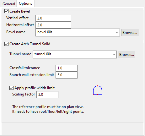
Start by clicking the option labelled Create Arch Tunnel Solid.
NoteThe option Honour point ordering for floor and roof data, located at the top of the main panel, must be enabled for this option to be made available.
To create an arch tunnel, the inputs that need to be supplied are floor and roof strings, external boundary strings, internal boundary strings, and a design shape.
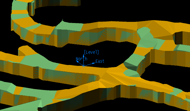
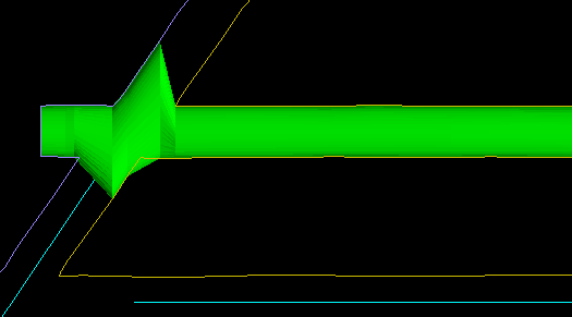
In the diagram below, the roof string superimposes the floor string.
Note: Notice that the tunnel shape is also loaded onto the screen (labelled as the Design Reference shape in this example.) You will need to identify this shape during the selection process. The tunnel reference shape was created using the Model > Primitives > Create/Edit Primitives option, then saving the chosen shape as a layer.
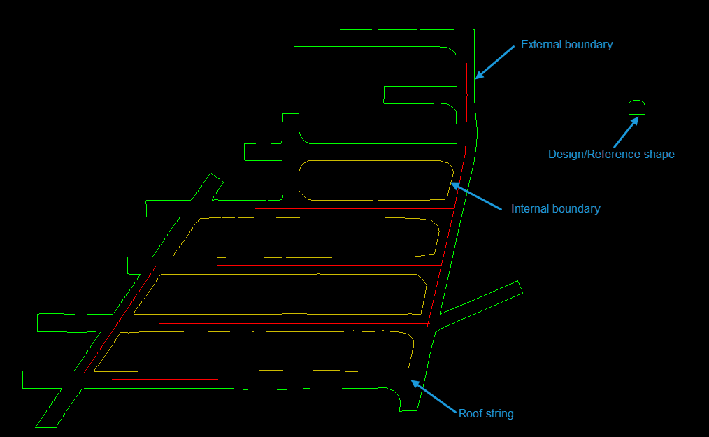
Figure 2: Input strings for creating arch tunnel solid.
-
Enter a name for the resultant tunnel in the textbox labelled Tunnel name.
-
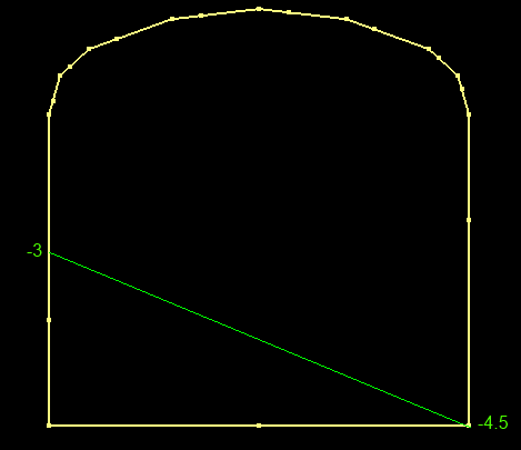
Next, enter a Crossfall tolerance value. The crossfall represents the slope of the floor from one side of the tunnel to the other.
The boundary points are ignored when the crossfall exceeds this value.
-
Enter the maximum distance between the intersection of two floor lines at T or Y intersections and the opposite wall into the textbox labelled Branch wall extension limit.
If the real distance is less than this limit, the branch tunnel stops at the intersection point.
If the real distance is greater than this limit, the tunnel continues until it meets the opposite wall.
-
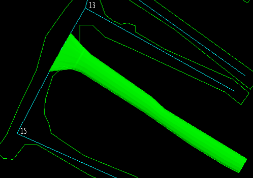
The tunnel shape can also be refined by using the Apply profile width limit option. However, there could be some missing parts because the solid doesn't cover the overall tunnel.
The profile width limit is dependent on the profile width and the scaling factor and can be enumerated as:
Limit = Scaling factor x Profile width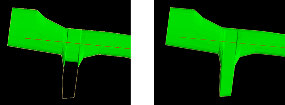
Figure 3: Tunnel shape with limit on left; tunnel shape without limit on right.
-
Select OK when you have finished entering all your input parameters.
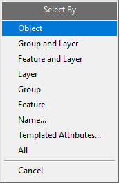
The Multiple Selection option is then displayed. You will be prompted to select the reference shape first (if you are creating an arch tunnel), followed by the roof string, floor, then the external wall, and lastly the internal wall. You can cancel between each selection to move to the next selection mode.
 Note
NoteYou can exit the Select By menu at any time by right-clicking or clicking Cancel on the Select By menu.
Object
Click on the object(s) that you want to select. When you finish selecting objects, right-click to return to the Select By menu.
Group and Layer
Click on an object that is part of the group and layer combination that you want to use to select. When you are finished selecting combinations, right-click to return to the Select By menu.
Feature and Layer
Click on an object that is part of the feature and layer combination that you want to use to select. When you are finished selecting combinations, right-click to return to the Select By menu.
Layer
Click on an object in the layer that you want to use to select. When you are finished selecting layers, right-click to return to the Select By menu.
Group
Click on an object in the group that you want to use to select. When you are finished selecting groups, right-click to return to the Select By menu.
Feature
Click on an object that has the feature that you want to use to select. When you are finished selecting features, right-click to return to the Select By menu.
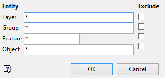
Name
Enter any combination of Layer, Group, Feature, and Object names that you want to select. To include all names for a particular attribute, enter an asterisk ( * ) for that attribute. If you want to exclude a layer, group, feature, or object by name, click the Exclude check box next to the name. Click OK to save selections, and then click Cancel to return to the Select By menu.
Templated Attributes Use this option to display the Select by Attribute panel. All
Click All to select all objects.
There are certain criteria for good input strings:
-
Floor/Roof strings shouldn't cross boundaries.
-
The points on floor/roof strings should lie in the middle of the tunnel.
-
There should not be any overlapped tunnel, meaning there should be no more than one floor/roof string or boundary at a section view of the tunnel.
-
The design shape must be on a plane view.
-
The floor line should stop when it meets the opposite wall.
Some examples of good and bad lines:
Corner:
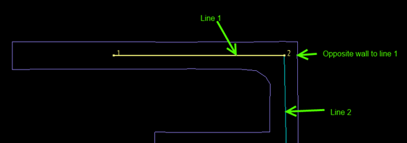
Figure 4: Good line.
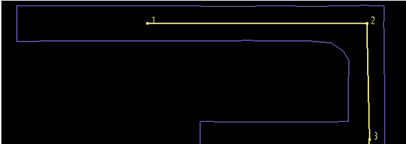
Figure 5: Bad line.
T-intersection or y-intersection:
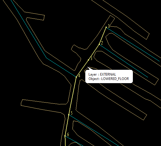
Figure 6: Good line.

Figure 7: Bad line.

