Load To 3D
This option is used to load and display as objects in the Primary Window, and data from either the structural database or the Stereonets Window.
The 'TYPE' and 'DIP' geotech schemas (if found in the .scd file) will be automatically used for the strike and dip when loading 3D data. If these schemas are not present, or to use different schemas, then you will need to use the Set Up 3D Display option before loading the data.
Placing the mouse cursor over a Geotechnical structure will allow you to view its details, including the structure name, code, dip and dip direction, etc. To display the Geotechnical information via a datatip, enable the Display datatips preference (under the Tools > Preferences > Graphics option).
Instructions
On the Geotech menu, point to Display, then click Load To 3D.
If a structural database has not been opened prior to selecting this option, the Open Structural Database panel displays first.
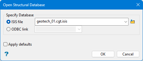
Isis file - Select this option to nominate an Isis database. The available drop-down list displays all Isis database files found within your current working directory. Click Browse to select a file from another location.
ODBC link - Select this option to nominate an ODBC link database. Select the design name from the drop-down list.
Apply defaults - Select this check box if you want to apply Vulcan's internal default settings when opening another structural database within the current Vulcan session. If this checkbox is not ticked, the settings that were used with a previous structural database will be used instead.
Note: We recommend that you use this option when opening another structural database from the same work area. This will allow you to clear any setup changes that you may have made.
Select OK.
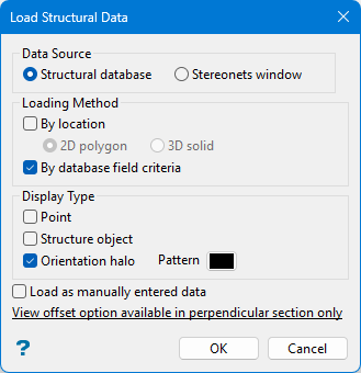
Data Source
Structural database - Select this option if you want the structural data to be loaded directly from the structural database.
Stereonets window - Select this option if you want the structural data to be loaded from the Stereonets Window.
The data to be loaded can be displayed asstructure objects,orientation halosorpointsas described below.
Loading Method
Structural data can either be loaded by location and/or by database field criteria. The By location option to load by 2D polygon or 3D solids (data to be loaded will be limited to a nominated polygon or triangulation respectively). The By database field criteria option to specify the criteria for the value of any field in the database.
By location - Select this check box if you want to load the structural data by a 2D polygon or 3D solids.
2D polygon - Loading by 2D polygon allows you to select a polygon in the Primary or Stereonets Window, and limit the selection of structural data to within that polygon.
3D solid - Loading by 3D solid allows you to select a solid triangulation in the Primary Window and limit the selection of structural data to within that solid triangulation.
Only one polygon can be selected when loading structural data.
Transferring from one window to the other is done 'from' a polygon or solid. Therefore, if you are loading from the Primary Window and you choose the By location option, the polygon selected will be in the Primary Window.
Visible structural data only is transferred from the Primary Window.
By database field criteria - Select this check box if you want to specify criteria for the value of any field in the database. This criteria must be met for the structural data to be selected for loading.
Display Type
Points - Select this option to display the data as normal Vulcan points. It is useful when using structural data for surface modelling. For example, in pit mapping.
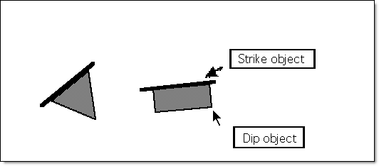
Structure object - Select this option to display the data as a 3D geotechnical PRIMARY VIEW symbol. The symbol consists of two objects: a strike-line object and a dip object. These two objects are coloured and scaled according to the values specified in the Set Up 3D Display option. The strike-line is usually a simple line segment, but the dip object varies according to the type of structural feature it represents. Together they indicate the orientation of the structure (i.e. the strike line is orientated 90 degrees to the dip direction).
All structural objects are created in predefined layers. If the structural objects are to be saved in other layers, then they may be copied using the Design > Layer Edit > Copy option.
The centre point of the strike-line is the true location (Easting, Northing and RL) of the structural feature. The angle formed between horizontal and the dip object is equivalent to the dip value; the dip object will be pointing in the dip direction (i.e. at 90 degrees to the strike-line).
Note: Structural features with negative dip values will always be orientated to face in a downwards direction by converting the dip value to be positive, and adding 180 degrees to the dip direction. If the dip direction is greater than 360 degrees, then the structure is assumed to have an unknown orientation. It is recommended that 999 be assigned to the dip direction to denote this case.
A variety of 3D structural data are supported, each of which have a corresponding Stereonet object. Refer to the Overview.
Orientation halo - Select this option to display the data as either a shape or an ellipse. It is scaled according to the values specified in the Set Up 3D Display option. For example, all faults could be displayed as ellipses scaled according to the degree of throw. The greater the throw, the larger the orientation halo, allowing the throw for each fault to be clearly seen.
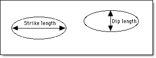
If the throw value is 2, a scale of 1:20 for the strike length and 1:10 for the dip length creates an ellipse that is 40 by 20 in the default units of measurement.
Each halo has the orientation of the structure it represents, and is coloured according to the strike colour legend set in the Set Up 3D Display option.
Note: The orientation halos may also be displayed with no scaling (i.e. using the same dimensions as the 3D structural symbols), by either loading them as manually entered data or indicating that no scaling is required (see the Set Up 3D Display option).
Load as manually entered data - Select this check box to load the data as manually created structure objects, i.e. without a link to the structural database. This allows you to load, for example, all the faults from a structural database as manual and some other type as normal, thus ending up with data in two different layers. This data can then be manipulated separately.
Apply section view offset - If you are in perpendicular section view, check this box to apply a section view offset that is relative to the current viewing plane. If ticked, then you will need to specify the offset value.
Select OK.
At this point, the next panel to display will depend on whether the By database field criteria check box was selected.
The loading process is then started. Press [Esc] to cancel.
If you ticked the By database field criteria checkbox, the Selection Criteria Entry wizard starts, starting with the panel below.
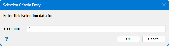
Selection Criteria Entry panel - Header
Enter the database key to be used for the highlighting, or accept the default asterisk for all.
Note: Only one bench/level area can be entered for each highlighting process. To select data from more than one mining area, select the By database field criteria option again.
Select OK.
The following Selection Criteria Entry panel is then displayed.
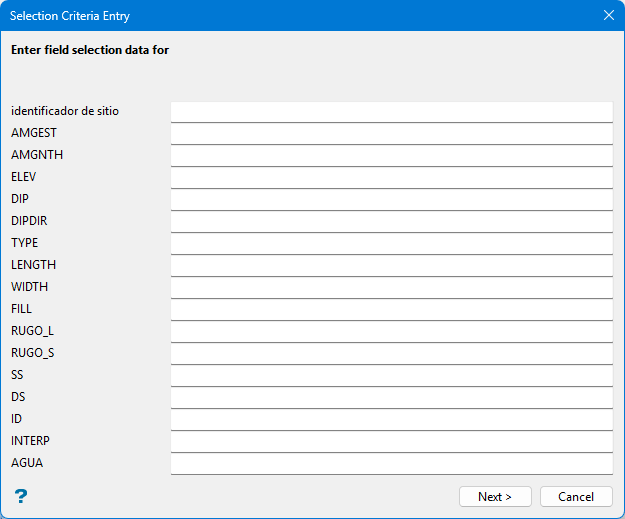
The number and naming of the rows in this panel depend on the fields contained in the currently loaded geotechnical database.
The maximum number of records that can be shown on this panel is 20. Therefore, if each record in the structural database contains more than approximately 20 fields, there may be more than one panel displayed.
If the By database field criteria check box was not ticked, the following Limited Selection Criteria Entry panel will be displayed instead
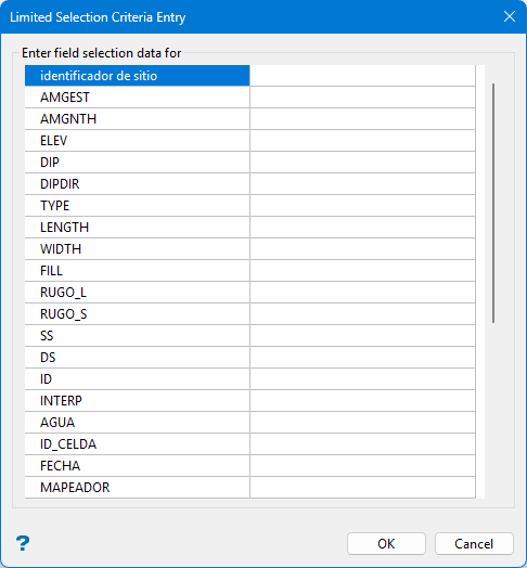
Limited Selection Criteria Entry panel - Geotechnical Data
Both the Selection Criteria Entry and Limited Selection Criteria Entry panels allow you to enter the desired values for any field in the database. Note that on the Limited Selection Criteria Entry panel, there are also three Restrict to Type fields available that allow you to up to three type codes by description.
Note: The criteria entered in these panels must be met by an entry in the database before the corresponding structural data can be selected and displayed.
Values can be entered as a range (45-65), or as a single value (45). If no value is entered in a field, Vulcan assumes that no restriction is to be enforced for that field. If no values are entered in any of the fields, Vulcan assumes there are no restrictions.
Note: Entered values remain in the drop-down lists until removed. This means that the next time you enter selection criteria, you will need to check for unwanted selection values in each drop-down list. To remove a value for a field, move to the required field and space over the existing values.
The following is an example of search criteria:
Mining Area:  Lower
Type       :  F
Dip        :  45, 70
Throw      :  0, 10 & 30, 40
Spacing    :  0, 15
This will select all faults dipping between 45 and 70 degrees that have a spacing value between 0 and 15 and a throw value that is either between 0 and 10 or between 30 and 40.
The numeric field value ranges are separated by ampersands (&) and the start and end values for the ranges by commas. All character values are separated by commas. The search is case-sensitive (that is'LOWER' is different to 'Lower'), multiple spaces are ignored and wildcards may be used (for example 'LOW*', 'LOW%R').
Select OK.
If you are loading from the Stereonets Window, then you are moved to the Stereonets Window (if not there already) and prompted to select a layer to load the structural data from. You must either select a pole point, plane line or 3D plane displayed on a Stereonet in the Stereonets Window (see the Load option under Stereonets for descriptions of these). All structural data in the layer containing the object selected is transferred to the Primary Window and loaded there. Manually entered data in the Stereonets Window cannot be transferred to the Primary Window because it has no associated 3D location (Easting, Northing etc.) information.
Note: Point data (i.e. data with no associated orientation information), if it exists in the structural database, will never be present in the Stereonets Window. It must therefore be loaded directly from the structural database to be displayed in the Primary Window.

