Define Method 
Use the Define Method option to define a method for modelling structural or quality variables.
Instructions
On the Grid Calc menu, point to Edit Modelling Defaults, and then click Define Method to display the Define Method panel.
Method
Enter the name of the modelling method (a maximum of 6 alphanumeric characters). The name should begin with a character.
Define
Select this option to create or modify the chosen modelling method.
Delete
Select this option to delete the chosen modelling method.
Click OK.
The following panel is then displayed.
If the method specified through the Define Method panel is new, then you will be asked whether or not to create the method before the Method Definition panel displays. Select Create to proceed to the Method Definition panel, or Cancel to exit the option.
This panel must be completed to create new methods defining specific parameters used in the structural or quality modelling processes.
Base Method
Select the base method on which to build your method. It can be one of the standard methods (Triangulation, Inverse, Least Squares, Spline) or a calculation. You should only use Triangulation or Inverse Distance when creating a stratigraphic model. The Least Squares method is not a data honouring method and the Spline method cannot work with mapfile data. Refer to the Grid Model option (under the Grid Calc > Model submenu) for an explanation of the various methods./dd>
You can specify any of the method specific parameters, trending, smoothing and masking. Apply fault is not supported and does not affect the modelling.
Method Specific Parameters
Maximum triangle side length
Only applicable to Triangulate
Enter the maximum triangle side length. Any grid node that falls in a triangle with a side length that exceeds this value is masked. The default is 'unlimited'.
Note: The default mask - the one that results from the data distribution and modelling technique - may (and can) be altered or replaced by subsequent masking processes, for example crop lines.
Power
Applicable to Inverse and Least Squares.
Enter the power to be used when calculating the weighting for the data points.
Number of Interpolative Points
Applicable to Inverse and Least Squares.
Enter the number of data points to use when interpolating values.
Note: If there are fewer points available than the number of interpolative points specified in the data set being modelled, then the number of available points will be used as the specified number of interpolative points. This means that a model will always be produced.
Maximum search distance
Applicable to Inverse and Least Squares.
Enter the maximum distance in which to search for interpolative points. Nodes that require points further than this distance are masked. However, they do have interpolated values derived using all the required points regardless of the distances, and such nodes may easily become 'visible' should the default mask be altered.
Spline Tension
Only applicable to Spline.
Enter a value for the spline tension. A negative value relaxes the splines, therefore the higher the negative value the more relaxed the splines will be, i.e. they curve more. A positive value increases the spline tension, it makes the splines pull tight over the control points, reducing, for example, the height of the tops of hills and the depth of valleys. The values are usually in the range of -3 to 3, but they can be more or less.
Horizontal spline, bias
Only applicable to Spline.
Enter the amount of bias in the horizontal splining. See also the Grid Model option - Hbias.
Vertical spline, bias
Only applicable to Spline.
Enter the amount of bias in the vertical splining. See also the Grid Model option - Vbias.
General Parameters
Calculation Equation
Only applicable if you have chosen to use Calculation as your modelling method.
Enter the equation with which to calculate a new grid.
Trend Order
Enter, or select from the drop-down list, the triangulation trend order. See the Trend option (under Data) for more information.
Smoothing Passes
Enter, or select from the drop-down list, the number of smoothing passes. See the Smoothing option for more information.
Options
Masking
Select this check box to control the masking instead of using the default.
Apply Faults
Select this check box to apply the faults that were defined through Load Fault Strings option (under the Grid Calc > Faults submenu).
Log Normalise
Select this check box to log normalise the data points. Each data value will be converted to its base 10 logarithm. This is particularly useful for modelling data with extreme variation, for example resistivity. For example, if the data points range between 10 and 1000, then after log normalisation they will range between 1 and 3.
Bias
Select this check box to apply extra bias to grid cells adjacent to data points.
Click OK.
The specifications are written to a temporary file. Use the Save Grid Specifications option to save the specifications.
If you selected the Masking check box, then the Mask Definition panel displays before the specifications are written to the temporary file.
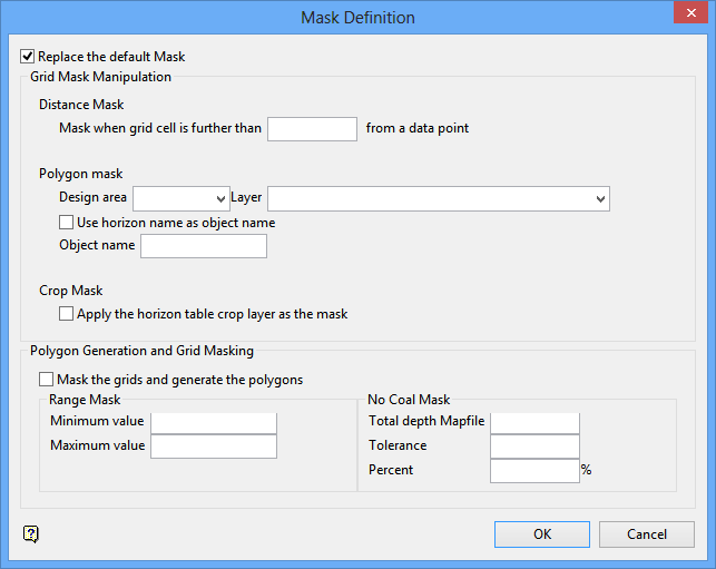
Replace the default mask
Select this check box to replace the default mask. The default mask limits the model to the extent of the drillhole data, i.e. the masked grid shows no extrapolation beyond the data extent. A mask of this type is created automatically every time a grid is generated in Grid Calc.
Grid Mask Manipulation
Distance mask
Enter the masking distance. This means that if a grid cell is greater than the masking distance away from a grid point, then it will be assigned a mask value of '0', i.e. it will be masked.
Polygon mask
Use this section to mask the grid cells that fall in a limiting polygon. Grid cells that fall in a clockwise polygon are assigned a mask value of '1'.
Design Area
Enter, or select from the drop-down list, the design database area name for the database that contains the limiting polygons layer.
Layer
Enter, or select from the drop-down list, the name of the layer for the limiting polygons. If underscores were used when naming layer used for masking, then the <proj><area>/gdc_spec file must be edited and the underscores added to the mask name.
Use Horizon name as an object name
Select this check box to use the horizon name as the object name.
Object name
Enter the object name or use a wildcard (* multiple character or % single character) to select the objects in the layer.
Crop Mask
Apply the Horizon Table Crop Layer as the mask
Select this check box to use the limit polygon layer defined as the 'crop layer' in the Horizon Table as the mask polygon.
Polygon Generation and Grid Masking
Mask the grids and generate the polygons
Select this check box to apply the masks to the grids and generate the polygons.
Range Mask
Enter the minimum and maximum values. Grid nodes outside this range are masked.
No coal mask
Use this section to create polygons around drillholes that do not contain the seam.
Total depth mapfile
Enter the total depth mapfile that defines the bottom of each drill hole, for example TD.
Tolerance
Enter the tolerance.
For example: 0 - drill hole must touch seam floor at total depth; -3 - hole must penetrate 3 metres before the drillhole is eliminated.
Percent
Enter a percentage for the polygon area. For example, 50 - creates the polygon half way between drillholes.

