Splits Definition
Use the Splits Definition option to specify the relationship between splits and merges (horizons must have been named and their relative order specified in the Horizon Table option). This information will be added to the <proj>.gdc_glob file.
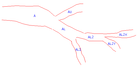
Figure 1: Graphical View
The lowest level of split is specified in the left column (which is headed "Horizons") of the panel. The horizons into which that horizon merges are specified in the right column (in the order of merging) and is headed "Merges Into". Merged seams are separated by commas.
Note: A seam cannot appear in both columns.
Using the example in Diagram 1, the entries on the panel would be:
|
Horizons |
Merges Into |
|
AU |
A |
|
AL1 |
AL,A |
|
AL2X |
AL2,AL,A |
|
AL2Y |
AL2,AL,A |
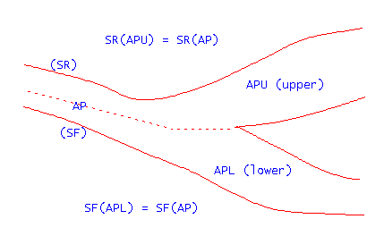
Figure 2: Graphical View
Instructions
On the Grid Calc menu, point to Edit Modelling Defaults, and then click Splits Definition to display the Define Splits panel.
Splits table
Horizon
Enter, or select from the drop-down list, the horizon name (lowest level split).
Merge Into
Enter the horizon(s) into which to merge, separated by commas.
Run FIXMAP
Select this check box to run FIXMAP (upon completion of this panel). FIXMAP is a utility that takes a set of standard Vulcan stratigraphic mapfiles and produces a new set. Values are interpolated for missing horizons by estimating the position and thickness of each horizon in each hole using the inverse distance method. It is also possible to run FIXMAP from the command line.
Selecting this check box will let you access the following tabbed panels:
- Data
- Horizons
- Limits
- Output
Data
Null value
Enter the mapfile null value. The default value '-9.00'.
Number of sample points
Enter the number of sample points to be utilised in the interpolation process. The default value is '10'.
Inverse distance power
The Inverse Distance Weighting method is typically used for modelling thickness and quality information. This method searches concentrically about each grid node for a minimum number of points to use to interpolate the grid node value. The number of points (NOIP) used and the distance to search for these points is specified as part of the method parameters. You can also divide the area into a maximum of 8 sectors, forcing the program to find the closest points in each sector, which is useful if the drillhole data is predominantly found in one section of the modelling area.
This method should not be used on faulted datasets or for deposits where the bedding planes are thin.
The grid node values are determined by taking a weighted average of the collected data points. Therefore, the closer a drillhole is to the grid node, the greater the effect it will have on the calculated node value. The weighting used is the inverse of the distance to the nominated power (the default value is 2).
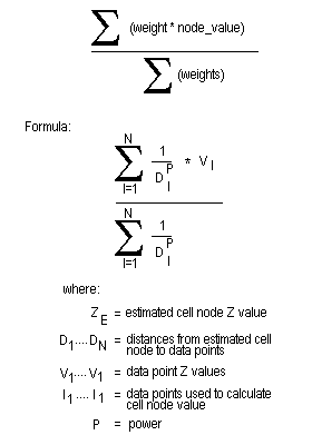
Figure 3: Inverse Distance Calculation
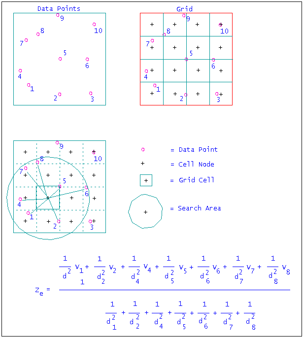
Figure 4: Inverse Distance Example
Use thickness if evaluations are null
Select this check box to use SK and TK as minimums when SR and SF are null. Fixmap uses ST, SF, TK, and ST values from the original structural mapfile. A null in any of these columns implies that the value is unknown and must be interpolated. If SR and SF are null, then the default action is to ignore TK and ST. If this option is used, in those instances where TK or ST are non-null, the value is used as a minimum thickness.
Don't re-interpolate after fixing splits
Select this check box if you do not want to re-interpolate after fixing the horizon positions. Using this option will also allow you to enable 'backwards compatibility'. This means that any mapfiles generated through this option will be forced to agree with mapfiles generated in previous versions of Vulcan (prior to version 3.5x). In normal usage this check box should not be selected.
Horizons
Pinch out horizons
Use this section to generate zero thickness (pinched out) horizons where the seam does not exist. Select the horizons to pinch out from the list at right.
Preprocess horizons
Select the horizons that you want to pre-process. The vertical position of these horizons will be assigned first, and all other horizon positions will be fixed later.
Limits
Mask database
Select the design database that contains the horizon limit polygons. These polygons will be used to pinch the horizon to zero thickness at drillhole locations outside of the polygons.
Mask layer template
Enter, or select from the drop-down list, the template name, that is, the naming convention for the limit layers. The name consists of a label with the two characters '%S' (or '%s') embedded. The %S is replaced with the horizon name to determine the appropriate layer name, for example, :LIMIT.%S becomes LIMIT.AU, LIMIT.AL1, etc.
Output
Quality map file suffix
Enter the suffix for the quality mapfile. These mapfiles will reflect the horizon positions defined by Fixmap. Leave this field blank if you do want to generate quality mapfiles.
Dump to DBL
Enter a name for the resulting Database Listing file (.dbl). The default value is 'fixmap'.
Click OK.
The relationship between splits and merges is then added to the global parameters (<proj>.bdc_glob). If you have chosen to run fixmap, then a window displays and Fixmap is run.

