MASK () Function
The Mask (expression) function can be thought of as a grid. The expression passed to the function determines the grid value at any point.
The mask flag is determined as follows:
If the expression passed to the mask function evaluates to 0 (zero, which means false), then the mask bit associated with that point will be zero. The mask bit will be 1 (one, which means true) for all other cases. A mask bit set to 1 (one) will be visible (on) and a mask bit set to 0 (zero) will be invisible (off) when viewing a masked grid.
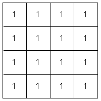
Mask(1) is equivalent to a grid of 1's everywhere, with all mask bits set to one (on).

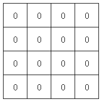
Mask(0) is equivalent to a grid of 0's everywhere, with all mask bits set to zero (off).

Relational Operators
To make effective use of the Mask function, logical expressions can be used. A logical expression always returns a value of one or zero, which are equivalent to true and false. Hence the expression -1 gt 2 evaluates to zero (false), and 1 lt 2 evaluates to one (true).
The relational operators are Lt, le,gt, ge, and, or, xor, eq, ne and not. The function mask ( tk gt 2 ) represent a grid of ones and zeros (since the logical expression always returns ones and zeros), but everywhere tk is not greater than 2, the grid value is not only zero, but the mask flag associated with that point is also zero, that is, set to off.
The mask function need not contribute quantitatively to the expression, but can be used to modify the resultant mask.
edit tk+0*mask(tk gt 2)
In the above example, it is best not to multiply the tk grid by the mask function directly since that would set the tk values to zero. If the tk values themselves (as opposed to the mask flags) are not set to zero, then the mask may be modified again without having to regenerate the grid.
The Mask Node value is used to combine grid models to define the total coal roof or floor surfaces. The "Z" values in masked nodes are used directly unless an alternative value is provided through the Project Defaults option (under the Grid Calc > Edit Modelling Defaults submenu). For simple arithmetic between surfaces, use "DEFAULT" as the masked node value - this is the current interpolated value at each node. When computing the lower boundary of several surfaces, set the masking mode to "OR" and use a large mask node value such as "9999." Use the minimum function to combine the grids: min(g1, g2, g3, g4).
When computing the upper surface of several surfaces, use a small mask node value such as "-9999." Utilise the maximum function to combine the surfaces: max(g1, g2, g3, g4). When summing thickness grids, set the masking mode to "OR" and use "0" as the mask node value.

