Rotating the View
There are four tools that you can use to rotate 3D data:
All of these tools can be found on the Graphics toolbar.
It is possible, through the Graphics : Input section of the Tools > Preferences option, to set the default rotation mode, which means once the rotation centre has been selected, you will automatically be placed in the default mode. You can also specify the point on which you want to centre the mouse movements. This point can be the rotation centre or the screen centre.
To return to the plan view, use the Reset View button  on the Graphics toolbar. This button has four levels of removing view changes. Firstly sections will be removed, then the exaggeration will be returned to the default exaggeration, then rotations and then any panning and zooming. If all you have done is rotated the view, then one click on the Reset View button will return you to plan view. If you have also zoomed or panned, then the first click will return you to the plan view and then second click will remove the zooming and/or panning.
If you are using the Enable dynamic display button  on the Effects toolbar, then the view will change dynamically as you click on the Reset View button . Otherwise the view will switch to the reset view.
The R key can be used to enter your default rotation mode. If you are already in another rotation mode, for example Virtual Sphere, Rotate Ortho or Ortho Sphere, then pressing the R key will allow you to toggle between the centre of screen and the centre of rotation.
Clicking with the mouse, while holding down the Ctrl key, will also allow you to enter your default rotation mode. Use the Alt key, instead of the Ctrl key, to use the most recently defined rotation centre. Release the Ctrl and Alt keys when you are ready to exit the rotation mode.
Ortho Rotatation
This rotation tool allows you to rotate around designated axes. Once you have selected your centre of rotation (using the Rotation centre button  on the Graphics toolbar ), click once and then move the mouse to rotate the data. Use the [Enter] key to exit the rotation mode.
An 'x' will mark the point on which the mouse movements are centred (either the screen centre or the centre of rotation depending upon your default settings) and a set of axes (the labels will depend on the type of grid selected in your project specification file (.dg1), X, Y and Z will be used for Orthogonal and Lat, Long and Level will be used for Geographic) will mark the rotation centre.
|
Mouse and Hotkeys |
Action |
|---|---|
|
X, Y or Z |
To change X, Y and Z axis. |
|
U |
To rotate perpendicular to screen |
|
V |
To rotate around vertical. |
|
W |
To rotate in the plane of the screen. |
|
Middle and Left or P |
To enter panning mode. |
|
Middle and Right or S |
To enter zoom mode |
|
Left + Right or P |
Enters panning mode. |
|
Middle or S |
Enters Zoom mode. |
|
R |
Toggles between centre of screen and the centre of rotation. |
Virtual Sphere Rotation
This rotation tool allows you to use 'virtual sphere' rotation. This rotation enables continuous 3D rotation about an arbitrary axis (as opposed to the Rotate Ortho mode, which only allows rotation about a chosen axis).
Once you have selected your centre of rotation (using the Rotation centre button, the mouse pointer will change to a hand, click and the hand will appear to grab something, click and drag and you can rotate the data in any direction. When you release the mouse button the view will continue to rotate, to stop the rotation, click the left mouse button (which will leave you in the rotation mode) or use the [Enter] key, which will also exit you from the rotation mode.
An 'x' will mark the point on which the mouse movements are centred (either the screen centre or the centre of rotation depending upon your default settings) and a set of axes (the labels will depend on the type of grid selected in your project specification file (.dg1), X, Y and Z will be used for Orthogonal and Lat, Long and Level will be used for Geographic) will mark the rotation centre.
| Mouse and Hotkeys | Action |
|---|---|
|
Shift + V |
Makes sphere annotation visible > invisible. |
|
V |
Toggles "Perspective mode" on > off. |
|
R |
Toggles between centre of screen and the centre of rotation. |
|
F |
Exits "Panning mode" and "Zoom mode". |
|
Enter |
Exits virtual sphere rotation mode. |
|
Right + Middle or W |
Allows you to adjust the radius of the virtual sphere to the current mouse position. |
|
Left + Right or P |
Enters "Panning mode". |
|
Middle or S |
Enters "Zoom mode". |
|
Right or Z (Perspective mode only) |
Dragging the mouse down moves your data towards the view point, which increases its apparent size. Conversely dragging the mouse up moves your data away from the view point, which decreases its apparent size. |
Ortho Sphere Rotatation
This rotation tool allows you to use a combination of virtual sphere and rotate ortho rotation. Using this mode you can rotate about the X, Y and Z axis, the screen plane and any arbitrary axis. Once you have selected your centre of rotation (using the Rotation centre button), a sphere displays.
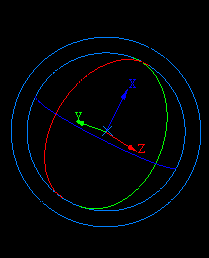
Figure 1: Ortho Sphere
The X, Y and Z axis as well as a circle representing the plane of each axis are displayed in different colours, i.e. in Diagram 1 the Z axis displays in red.
To use the rotate ortho mode, click on one of the circles representing the axes or the outer most circle and drag the mouse. When you release the mouse button the view will continue to rotate, to stop the rotation, click the left mouse button (which will leave you in the rotation mode) or use the [Enter] key, which will also exit you from the rotation mode.
When you hover the mouse over one of the circles, the cursor will change to the rotate ortho cursor.
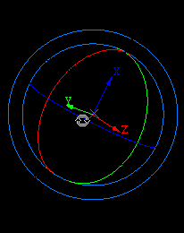
Figure 2: Rotate Ortho Cursor
The view will rotate about the selected axis or if the outer circle was chosen about the screen plane.
To use the virtual sphere mode, click anywhere on the sphere (not one of the circles) and drag the mouse. You can rotate the data in any direction. When you release the mouse button the view will continue to rotate, to stop the rotation, click the left mouse button (which will leave you in the rotation mode) or use the [Enter] key, which will also exit you from the rotation mode.
When you hover the mouse over the sphere, the cursor will change to the virtual sphere cursor.
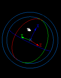
Figure 3: Virtual Sphere Cursor
An 'x' will mark the point on which the mouse movements are centred (either the screen centre or the centre of rotation depending upon your default settings) and a set of axes (the labels will depend on the type of grid selected in your project specification file (.dg1), X, Y and Z will be used for Orthogonal and Lat, Long and Level will be used for Geographic) will mark the rotation centre.
|
Mouse and |
Action |
|---|---|
|
V |
Toggles "Perspective mode" on > off. |
|
R |
Toggles between centre of screen and the centre of rotation. |
|
Z or Middle + Right |
Enters "Zoom mode". |
|
Enter |
Cancels out of the ortho sphere rotation mode. |
|
Left + Right |
Allows you to adjust the radius of the virtual sphere to the current mouse position. |
|
Middle or Left + Middle or P |
Enters "Panning mode". Pressing the P key will allow you to enter "Pan by Dragging mode". In Pan by Dragging mode you will need to specify the from and to points. |
|
Right (Perspective mode only) |
Dragging the mouse down moves your data towards the view point, which increases its apparent size. Conversely dragging the mouse up moves your data away from the view point, which decreases its apparent size. |
Z-Up Rotation
This rotation tool allows you to restrict virtual sphere rotation to ensure that the Z axis is always up and that the horizon remains horizontal when viewing topographical data. When selected, the view, if necessary, is altered so that the Z axis is up.
To rotate the view, click and drag. When you release the mouse button the view will continue to rotate, to stop the rotation, click the left mouse button (which will leave you in the rotation mode) or use the [Enter] key, which will also exit you from the rotation mode. Regardless of the position from which you dragged, the Z axis will always remain up.
An 'x' will mark the point on which the mouse movements are centred (either the screen centre or the centre of rotation depending upon your default settings) and a set of axes (the labels will depend on the type of grid selected in your project specification file (.dg1), X, Y and Z will be used for Orthogonal and Lat, Long and Level will be used for Geographic) will mark the rotation centre.
Refer to the list of hotkeys (shortcut keys) that relate to the Vulcan rotation modes.

