Overview - Model Menu
Vulcan offers four main data structures for modelling surfaces:
Each of these structures has advantages and disadvantages as to their ability to provide you with the best solution for your modelling requirements.
Strings
String and point data form the basic observational data of the geologist, engineer or surveyor and provides the basis for the derived data structures, such as triangulations, grids and block models. You can add your own interpretation to this data to control the resulting structure.
The data is usually supplied through survey, drilling or engineering design. However, although it provides the input to both triangulations and grid models, it does not, in itself, provide any continuous structure.
Grids
Grids are regular meshes of 2D surfaces. They only hold data at each grid node and as such cannot accurately represent detailed irregular data. Grids, however, are able to place mathematical estimates of the data values between data points. A variety of algorithms are available to provide these estimates.
Another advantage of grids is the speed of calculation between a series of grids, thus giving a powerful tool to develop surfaces or attribute grids defined by other grids estimated from raw data.
Each grid file contains only one "Z" or attribute value. This can be used to represent either true elevation or attribute for example quality or assay data.
Since there is only one value per XY location a single grid cannot represent overfolded or reverse faulted data.
Defined for a grid are:
- Minimum and maximum X, Y co-ordinates
- Grid cell size (constant in X and Y)
- Z value for each grid node
- Mask value 0 or 1
Masks
Grids can have masks that show which part of the grid is active, thus a irregular boundary, such as an outcrop or lease boundary, can be used to constrain the active area.
Advantages
- Grids are very fast structures for the storage of surface data.
- It is easy to manipulate the "Z" or attribute values.
- Grids of ratio, depth of cover, interburden, etc. can be formed by simple arithmetic calculation. More complex calculations can be performed in Grid Calc to produce complex grids, such as dip grids.
- Ability to use shading to highlight attribute values.
- Draping the attribute values of one grid on another can be a powerful analysis tool when comparing the spatial relationship of the two variables.
Disadvantages
- Complex structures with faults, overturns or other break lines cannot be adequately represented with grid files.
Creation
Grids can be created in Model > Grid Mesh Surfaces or in Grid Calc. A variety of algorithms are used and can be applied to the new data to generate grids. Grids can also be generated in Grid Calc by calculation from other grids.
SR = SF + TK
where
SR = Structure Roof,
SF = Structure Floor,
TK = Thickness.
or
Rt = TK/(TP-SF)
where
Rt = Ratio,
TP = Topography.
Applications
Grid modelling is particularly useful in relatively un-deformed stratigraphic deposits, such as coal. Regional studies of geophysical data can often be handled using grids.
Grids are used to provide a model that can be contoured. The grid is a step between the raw data and the contour.
A set of grids, i.e. a grid model, can be used in the reserving options of Vulcan to provide the inputs for mine design and scheduling.
Triangulations
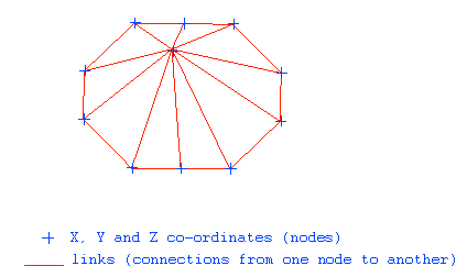
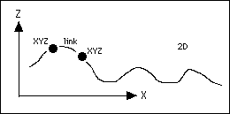
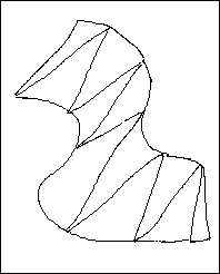
A triangulation file or structure is a series of 3D co-ordinates and links between them such that a series of triangle shaped planes is determined which, when linked, define a surface or enclose a volume.
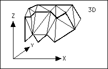
By using a triangulation structure a surface can be accurately defined in 3D space. The triangulation structure can therefore define a 2D or topographic surface or be enclosed such that a 3D or solid is represented by the data.
Triangulations accurately represent the observed data points since each data point is preserved in the triangulation structure. Breaklines that represent features, such as faults, pit toes and crests, are followed exactly.
Simple triangulations do not, however, add any estimates of the shape of the surface between raw data points. This means that where the raw data is sparse the triangulation will be coarse.
Algorithms have also been provided that allow you to estimate values between data points and provide a more intuitive shape to the triangulation surface.
Since triangulations are a series of 3D co-ordinates and the connections or links between them, it is quite possible for them to represent both 2D and 3D surfaces.
The versatility of the triangulation structure allows it to be used for many purposes. However, an understanding of its underlying concept is important when applying it to particular geological or mining situations.
Advantages
The main benefits of using triangulations are that they can accurately represent a surface. They can therefore be used to define such geological, geographic or mining elements as:
- 2D/3D topography
- Planned or actual mine excavations
- Geological surfaces
- Enclosed or solid ore bodies
- Underground development
- Stope shapes
- Arbitrary attribute models
- Ground water levels
Triangulations can give a high quality of 3D viewing so that you can rapidly illustrate the concepts of a geological model or engineering design.
The wide range of utilities that work on triangulations make them a very powerful modelling display and analysis tool.
Triangulations also provide a very efficient method of storing 3D shape information. Using an open pit design as an example, it is not necessary to store sections, plans and long sections as separate string files on disk. These strings can quickly and easily be retrieved from the triangulated pit model when they are required.
Triangulations can be stored into triangulation libraries which may be located in different directories. For example, all pit design triangulations in a pit design library.
Disadvantages
- It is sometimes difficult to force triangulations to represent correctly the true nature of a surface. This is especially the case if contours are triangulated. Flat spots can occur in the triangulations in spurs and re-entrants, thus giving a false picture.
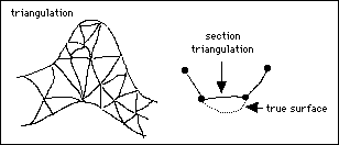
You can control these types of problems with the addition of control lines running along the crests of spurs or in the centres of gullies. This process may, however, be time consuming. Some options in Vulcan attempt to correct these problems but they do not satisfy all cases.
- Modelling of sparse data. Large flat triangles give a surface a coarse resolution, while grid modelling techniques, estimate values into the gap between the raw data points to give a smoother surface.
- Calculations between triangulations to give new surfaces are also less flexible than with grids. Adding two surfaces may result in large files with many triangles.
Creation
Vulcan offers two basic methods to create triangulations:
- 2D (surface)
- 3D (solid)
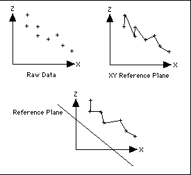
The2Dmethod uses as its core the Delaunay technique that, from a given distribution of XY points, fits a series of triangles such that each triangle attempts to be an equilateral triangle. This method is considered by many to provide the best triangulation of a set of data points for surface approximation problems (Correc and Chapuis 1987, De Floriani 1987b, McCullagh 1988, Sibson 1978, Watson and Philip 1984).
If strings are introduced to the raw data these strings provide breaklines across which triangles are not permitted to cross. The triangulation may then more accurately represent the actual surface where sharp changes of slope have been recorded. However, these breaklines cause the triangulation not to be a true Delaunay triangulation.
The default for the 2D triangulation is to view the data with respect to the XY or horizontal plane. You can, however, define a different plane as the reference for the triangulation.
3Dtriangulations are generated by linking strings together in a controlled sequence. The default algorithm causes the links to be generated in such a way that the minimum surface area is formed. As with the 2D triangulation, you can affect the links by forcing certain points on adjacent strings to be linked.
The linking of strings allows the resulting triangulation to be overturned or enclosed as a solid. This is not possible with the 2D method.
As triangulations created by both methods are stored in the same file structure, many utilities can work on either type of triangulation. The utilities are found in the Triangle Utility and Triangle Edit menus. Some utilities only work sensibly on a 2D or 3D structure and these are therefore found in the respective Triangle Surfaces and Triangle Solids menu.
Applications
The triangulation structure has become a core feature of Vulcan and is typically used to represent:
- Topography
- Geological surfaces (structures and faults)
- Excavation surfaces (planned and as actual)
- Underground mine development
- Mining blocks
- Arbitrary attribute surfaces
- Buildings
Use of the intersection, relimit and arithmetic tools let you rapidly generate new triangulations that accurately represent elements of the geological or mine design.
Main uses of triangulations are to:
- Give accurate volumes, either between two 2D surfaces or in a solid.
- Evaluate the reserves from a block model in a triangulated solid.
- Develop mine designs.
- Visualise geological features or development designs.

