Grid Mesh
Construct a Grid Mesh Model
Use the Grid Mesh option to construct a grid mesh model using a loaded triangulation.
Instructions
On the Model menu, point to Triangle Surface, and then click Grid Mesh.
Select the triangulation. The triangulation model will be selected automatically if there is only one loaded onscreen.
The following panel is then displayed.
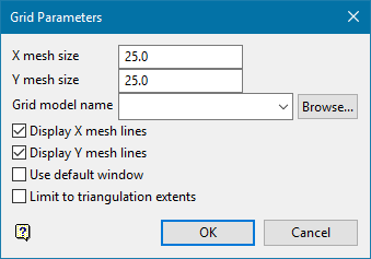
X/Y Mesh Size
Enter, in real world co-ordinates, the X and Y grid spacing.
Grid model name
Enter the grid model identifier (<gfi>) and optionally the model variable (<mv>) parts of the name of the model to be created. The maximum size is 20 alphanumeric characters (spaces are not allowed).
The full name is <proj><gfi>.<mv>g where <proj> = project, <gfi> = grid file identifier, <mv> = model variable and " g " denotes a grid mesh (compared to " t " for triangulations). If no model variable is entered, then the default <sf> is assumed.
Display X/Y Mesh Lines
Check these check boxes to display the grid lines.
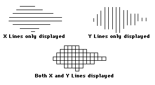
Figure 1: X/Y Mesh Lines
Use default window
Select this check box to create the grid model the same size as the default mapping window. If this check box is not selected, then you will be required to define the grid area once this panel is completed.
Limit to triangulation extents
Select this option to create the grid model limited to the size of the triangulation extents.
Click OK.
The grid mesh model is then created. If you didn't check the Use default window check box, then you will need to indicate the grid model origin and extent before the grid mesh model is created.

