Cut
Cut Triangulations
Use the Cut option to cut triangulations into two sections by interactively digitising a cutting line. The cutting operation can be modified by either projecting the string and triangulation against a plane and/or by applying an angle to the cut.
Instructions
Open the triangulation that you want to cut.
On the Model menu, point to Triangle Utility, and then click Cut to display the Cut Triangulations panel.
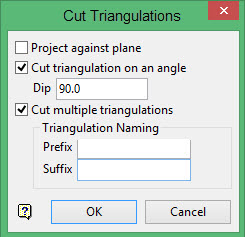
Project against plane
Select this check box to project against a nominated plane. The plane on which to project the cutting line is defined through the Projection Plane panel, which displays when the Cut Triangulations panel has been completed. If this check box is not selected, then the cutting line will be projected upon the XY plane.
Cut triangulation on an angle
Select this check box to apply an angle to the cut and enter the angle in the Dip box.
Cut multiple triangulations
Select this check box to cut through multiple triangulations using a single line. A prefix and/or a suffix can be appended to the names of the resulting triangulations. For example, ' <prefix><model name><suffix>.00t '. If both fields are left empty, then '_cut' will be appended to the end of the triangulation name.
Click OK.
Select the triangulations that you want to cut. If you selected the Project against plane check box, then the Projection Plane panel displays before you are asked to nominate the necessary triangulations.
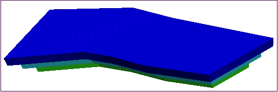
Figure 1: The Original Triangulations
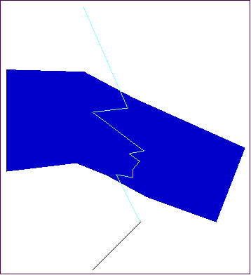
Digitise the cutting line. (See Designing a Line and Digitising for more information about creating and digitising a line.)
The cutting line must not cross itself and must start and end outside the extent of the triangulation. For triangulations containing multiple shells, the cutting line must start and end outside the extent of the entire triangulation not just the extent of the shells being cut.
When digitising the cutting line, you cannot snap onto the triangulation. Therefore, you may prefer to create the cutting line before using this option and use the Snap to Point s mode when digitising the line to snap to the existing line.
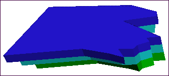
When your line is complete, right-click to exit the line creation process and cut the triangulation. The triangulation is then cut using the line you created, and one of the new triangulations displays.
Select an option on the Cut menu that displays.
- Click Save this part to save the triangulation that is currently displayed as a new triangulation. The Save Cut Triangulation panel displays to enter information to save the new triangulation.
- Click Swap to display the other triangulation resulting from the cut.
- Click Cancel to cancel the cut operation. This returns you to the digitising line prompt. Neither of the resulting triangulations will be saved.
After saving one of the new triangulations resulting from the cut, the second triangulation displays and you will be prompted to Save this part or Cancel.

