Auto Expand
Use this option to expand one or more surface triangulations. The expanded surfaces will be saved as new triangulations and are stored in your current working directory or, if applicable, another nominated storage location.
Instructions
On the Model menu, point to Triangle Utility, then click Auto Expand.
Follow these steps:
-
Select the Specification file (
.aef) that you want to open or, if applicable, edit. The drop-down list contains all (.aef) files found in the current working directory. Click Browse... to select a file from another location. To create a new file, enter the file name and extension. -
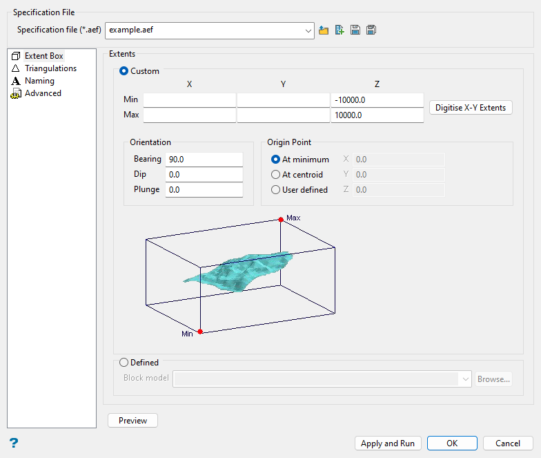
Use the Extents section to nominate surface triangulations that will be expanded outwards until they meet a nominated extents boundary or intersect another surface triangulation. The extents boundary can either be defined onscreen or through using the extents of a nominated block model.
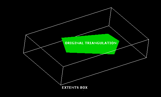
Figure 1: Auto Expand Extents Box
Select either Custom or Defined extents:
-
Custom: Select this option to use a custom extents boundary. You can either manually define the extents by entering the minimum and maximum X and Y coordinates, or dynamically define them using the Digitise X-Y Extents button.
Upon clicking the Digitize X-Y Extents button, you will be asked to digitise the extents onscreen. Indicate (by left-clicking) the lower left hand corner of the extent, followed by the upper right hand corner of the extent. The minimum and maximum fields in the Auto Expand Triangulations interface will now contain the appropriate X and Y values.
Minimum and maximum extents are defined with the assumption that the model is rotated at 90 degrees. This is the same default used by block model rotation.
-
Defined: Select this option to define the extents boundary using a nominated block model. The drop-down list contains all block models found in the current working directory. Click Browse... to select a file from another location.
-
-
(Optional) Click the Preview button to preview the Auto Expand Extents box. Once selected, the Auto Expand Triangulations interface will collapse and the Auto Expand Extents box will be displayed onscreen. Right-click with the mouse when you are ready to return to the Auto Expand Triangulations interface.
Triangulations
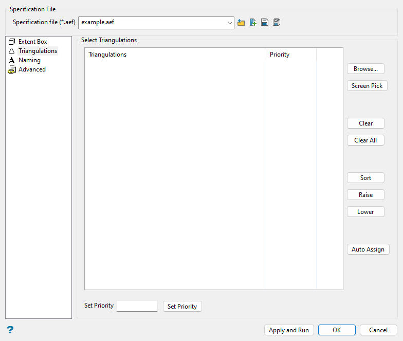
This section allows you to select the surface triangulations that you want to expand. The desired triangulations can either be selected directly from the screen or through browsing your available data directories.
Follow these steps:
-
Populate the Select Triangulations list using the Screen Pick or Browse... buttons.
-
Screen Pick: Select this option to pick the necessary triangulations from the screen. In order to use the Screen Pick button, you will need to load the surface triangulations onto the screen before running the Auto Expand option.
-
Browse: Select this option to display the Open panel and select the triangulations you want to load from the current working directory, or navigate to another location. To highlight multiple files that are adjacent to each other in the list, hold down the Shift key and click the first and last file names in that section of the list. To highlight multiple non-adjacent files, hold down the Ctrl key while you click the file names.
Move the items to the selection list on the right side of the panel.
- Click the
 button to move the highlighted items to the selection list on the right.
 - Click the
 button to remove the highlighted items from the selection list on the right.
 - Click the
 button to move all items to the selection list on the right.
 - Click the
 button to remove all items from the selection list on the right.
Click OK to add the selected triangulations.
- Click the
Note: We recommend that you confirm the directory path of the selected triangulations before pressing the Apply and Run button. If the nominated triangulations cannot be found, then an error message displays onscreen.
To remove a triangulation from the list, highlight the triangulation name and press the Clear button. To remove a group of triangulations, use the left mouse button in combination with the Shift key to highlight the triangulations (this is for triangulations that are adjacent in the list, for non-adjacent triangulations use the Ctrl key and the left mouse button) and select Clear. To remove all of the triangulations, select the Clear All button.
-
-
Set the priorities for the selected triangulations. Priority ratings are used to control which expansion operation takes precedence when intersections occur.
Priority values can either be assigned automatically (using the Auto Assign button) or manually. To assign a priority value manually, highlight the triangulation name (under the Triangulations list) before entering a value and pressing the Set Priority button. The higher the number the higher the priority, i.e. a priority of value
10overrides a priority value of1.Use the Sort button to sort the triangulations by priority value. Press the Sort button once to sort the priority values in descending order, press the button again to sort the priority values in ascending order. The Raise and Lower buttons can be used to increase and decrease the priority values for a highlighted triangulation.
ExampleIn the following example, three expansion operations are about to be performed. Surface A, B, and C have been assigned priority values 3, 1, and 2, respectively.
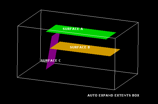
Figure 2: The Original Triangulations
Surface A will continue expanding until it reaches the edges of the Auto Expand Extents box. Surface B will continue expanding in all direction except the direction where it intercepts. Surface C will continue expanding in all direction except the direction where it intercepts Surface A. The translucent areas in the following diagram represent the expanded surface triangulations.

Figure 3: The Expanded Copies of the Original Surfaces
Naming
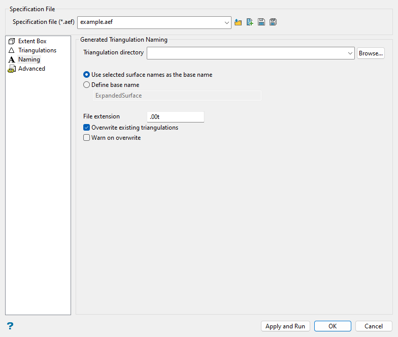
Follow these steps:
-
Select the Triangulation directory that will be used to store the resulting triangulations. Leave this field blank if you want to save the resulting triangulations within your current working directory. Alternatively, use the Browse... button to nominate a different storage location.
To save your triangulations within an existing triangulation database, use the Browse... button to locate the applicable (
.tri) folder. Once found, click on the file before clicking OK.If you want to store the triangulations within a subdirectory of your triangulation database, double-click on the (
.tri) folder to display the Select Directory panel. Once you have located the desired storage folder, click on the folder name before clicking OK. -
Select whether you want to Use selected surface name as the base name or Define base name.
-
Use selected surface name as the base name: Select this option if you want the expanded triangulations to be named after the original surface triangulations. A numeric value will be appended to the end of each triangulation name.
Example: If your original surface triangulation is named
MySurface.00t, and a file extension of.00twas specified, then the resulting triangulation will be namedMySurface001.00t. -
Define base name: Select this option to specify a base name for the expanded triangulations. The default base name is
ExpandedSurface. A numeric value will be appended to the end of each triangulation name.ExampleIf you use a base name of
ExpandedSurfaceand a file extension of.00tis specified, then the resulting triangulation will be namedExpandedSurface001.00t. Additional expanded triangulations would be namedExpandedSurface002.00t,ExpandedSurface003.00t,ExpandedSurface004.00t, etc.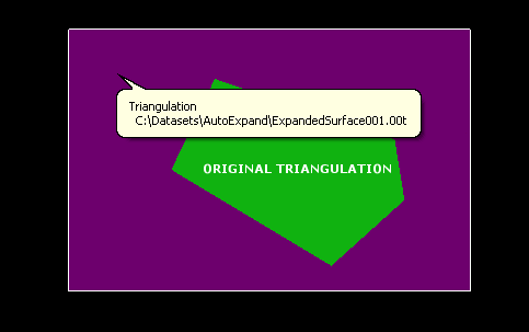
Figure 4: Using a Base Name
-
-
Enter the File extension that will be assigned to the expanded triangulation files. The default file extension is
.00t.Note: In order for triangulation files to be listed in the Vulcan Explorer application and through dialog boxes, their file extensions must be defined through the Vulcan Preferences option. Refer to the Triangulations section of the Vulcan Preferences option for more information.
-
Select the Overwrite existing triangulations checkbox if you would like to replace any existing triangulations that happen to share the same name as the expanded triangulations.
If this checkbox is selected, you have the option to enable Warn on overwrite, which allows you to be warned when an existing triangulation is about to be replaced. If this option is not selected, then you will not be prompted and the existing triangulation will be replaced.
Advanced
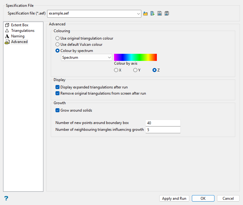
Follow these steps:
-
Select how you would like your expanded triangulation to be coloured:
-
Use original triangulation colour: Select this option to colour the triangulation using the colour of the original triangulation.
-
Use default Vulcan colour: Select this option to colour the triangulation using the default Vulcan colour (set through the Status toolbar).
-
Colour by spectrum: Select this option to colour the triangulation by spectrum. This means that the colour spectrum is stretched over the axis values. Use the drop-down list to select the desired spectrum.
If you select the Between two RGB values spectrum option, you will need to nominate two colours to stretch over the axis values of the triangulations. For example, if you select red and blue, then the small values would be red, the middle values purple, and the large values blue. The colour of the middle values is an average of the two chosen colours.
-
-
Select the Display expanded triangulations after run checkbox if you would like to display the resulting triangulations onscreen once they have been created.
-
Select the Remove original triangulations from screen after run checkbox if you would like to remove the original surface triangulations from the screen once the resulting triangulations have been created.
-
Select the Grow around solids checkbox if you want the expanded surface to grow around any triangulation solids that it happens to intersect. If this checkbox is selected, then holes will be created in the resulting surface. This method is very similar to the Keep outside option used through Model > Triangle Surface > Relimit by Solid.
ExampleIn the following diagrams, the nominated triangulation surface has intersected a cylindrical solid. The translucent areas in the following diagrams represent the expanded surface triangulation.
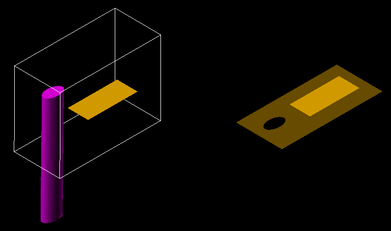
Figure 5: Grow around solids enabled
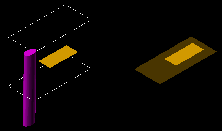
Figure 6: Grow around solids disabled
-
Enter a value for the Number of new points around boundary box field to specify the number of vertices added between the end points of each edge of the Auto Expand extents box. Increase this number for a more detailed extrapolation. The Z value of these vertices is calculated by registering the vertices onto a number of planes defined by neighbouring triangles (defined in the next step).
-
Enter a value for the Number of neighbouring triangles influencing growth field to specify the number of triangles that will be used to calculate the Z values of the set number of extrapolated vertices (defined in the previous step). This value should be set according to the amount of data in the surface. For a better extrapolation, use a larger number.
Use the Apply and Run button at the bottom of the panel to save the specifications in the nominated file before expanding the triangulation. Press the OK button if you only want to save the specifications before exiting the option. Click Cancel to exit the option without saving.

