Troubleshooting Guide
When using the Build 3D Drive or Generate option, you may encounter some problems along the way. This section describes some of the most common issues and gives solutions and workarounds to those.
The as-built triangulation has been built from the data created by the Generate option, but when checking the triangulation with the Model > Triangle Utility > Check option, the consistency and possibly other options checked on the tests are failing. When creating the as-built triangulation with the Build 3D Drive option, you chose to create bevels at the corners of the as-built.
Solution
Run only the Consistency check, saving the inconsistencies into a layer. In plan view, review the data, and you will see the problem areas. You may need to zoom in and make the triangulation invisible to better see the problem. The problem may be a stray point.
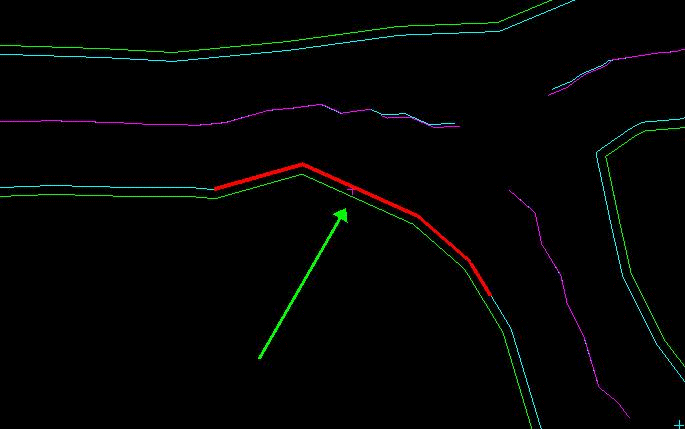
Figure 1: Stray Point
Remove points such as these using the Design > Point Edit > Delete option, deleting one point at a time. If you have many such points, then remove them using the Design > Object Edit > Delete by Polygon option. Choose to Delete by Object before picking the roof/back survey data, since the survey data is stored as one object. Be aware that you may do this for the roof/back survey data and for the floor/sill survey data.
After removing these points, clear the layer containing the polygons generated by the Build 3D Drive option, and rerun the option. This is then followed by checking the triangulation once again with the Model > Triangle Utility > Check option. If the Consistency test now passes, but the Self Intersection test (crossing) fails, then you will need to move on to solving that problem as through the following solution.
The as-built triangulation has been built from the data created by the Generate option, but when checking the triangulation with the Model > Triangle Utility > Check option, the self-intersecting and possibly other options checked on the tests are failing. When creating the as-built triangulation with Build 3D Drive, you chose to create bevels at the corners of the as-built.
Solution
Run only the Self Intersection check, saving the self-intersections into a nominated layer. In plan view, review the data, and you will see the problem areas. You may need to zoom in and make the triangulation and self-intersection marks invisible to better see the problem.
In Figure 2, the points were labelled through using the Analyse > Label > Point Label option. You can see that point number 1088 is causing the bevel polygon to contain an extra line segment that is not necessary. Remove this extra point (1088) using the Design > Point Edit > Delete option. In some cases, this extra line segment may be difficult to see. However, if there is a self intersection that has been flagged, even if you do not see an extra line protruding as in the diagram, try removing what appears to be extra points anyway.
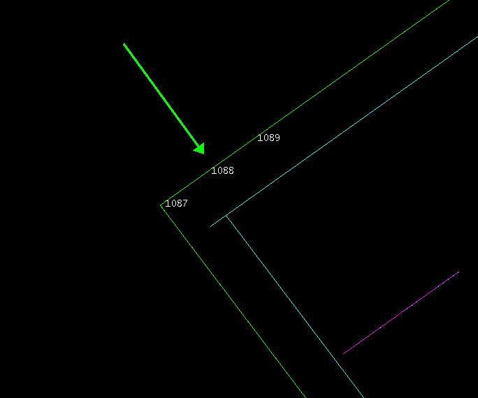
Figure 2: Bevel Polygon Containing Unnecessary Line Segment
Generally, you can remove the extraneous points using the Design > Point Edit > Delete option. However, if you find you have many extra points, then you might consider using the Design > Object Edit > Filter option, using a very small filter value, such as 0.05.
After removing extra points like these, clear the layer containing the polygons generated by the Build 3D Drive option, and rerun the option. This is then followed by checking the triangulation once again with the Model > Triangle Utility > Check option. If the Consistency and Self Intersecting tests now pass, but the Closure test fails, you now need to move on to solving that problem as described in the next problem.
If the Self Intersecting test still fails, but this time along the rib, not at the corner or end of a heading, label the sequence of the points as before. In some instances, if points along the wall/rib line are closely spaced, even if along a straight line, tolerances of point spacing in the triangulation program will cause crossing or self-intersecting triangulations to be formed. Remove points that are closely spaced in an area that has been marked as self-intersecting. Deselect the layer containing the polygons generated by the Build 3D Drive option, then run the option once again. It is likely the problem will be removed.
The as-built triangulation has been built from the data created by the Generate option, but when checking the triangulation with the Model > Triangle Utility > Check option, the closure and possibly other tests are failing. When creating the as-built triangulation with the Build 3D Drive option, you chose to create bevels at the corners of the as-built. When you look at the resulting triangulation, you note that a few triangulation facets are missing in places.
Solution
Run only the closure check, saving the closure boundaries (edges) into a layer. In plan view, review the data, and you will see the problem areas. You may need to zoom in.
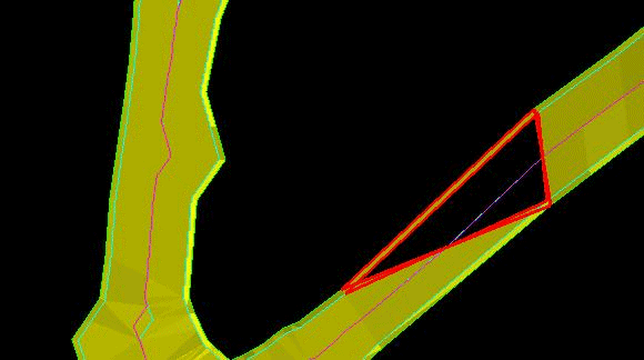
Figure 3: Missing Triangles
This sort of problem, in which a few triangulation facets are missing, can be solved easily by using the Model > Triangle Solid > Close Solid option. After running the Close Solid option, check the triangulation once again using the Model > Triangle Utility > Check option. All tests should now pass on the closed triangulation. If the triangulation is still open, then you may have another problem to deal with. See the next problem.
The as-built triangulation has been built from the data created by the Generate option, but when checking the triangulation with the Model > Triangle Utility > Check option, the closure and possibly other options checked on the tests are failing. When creating the as-built triangulation with the Build 3D Drive option, you chose to create bevels at the corners of the as-built. When you look at the resulting triangulation, you note that many triangulation facets are missing, leaving large gaping holes on the roof/back and floor/sill of the triangulation, not just one or two facets as in the previous problem.
In plan view, review the data, and you will see the problem areas. You may need to zoom in.
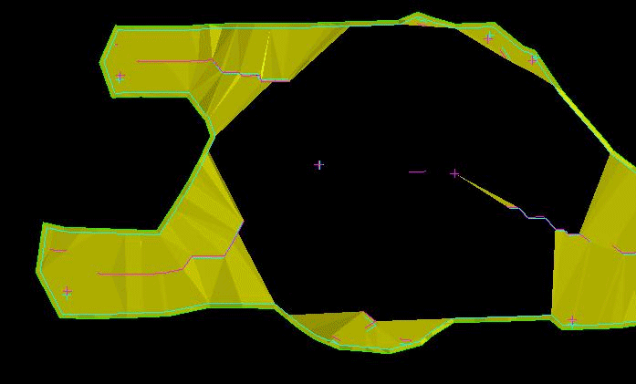
Figure 4: Open Triangulation
Solution
You may need to add survey data to the roof/back and floor/sill. This is easily done by snapping points (through the Design > Create > Point option) to the top and bottom of the triangulation that is used by the Generate option.
Make sure that what you digitised is in the same layer as the rest of the survey data created by the Generate option, and make sure that what you digitised is the same colour. Finally, use the Design > Object Edit > Coalesce option to put what you digitised into the same object as the data created by the Generate option. After adding the points, rerun the Build 3D Drive option.
The as-built triangulation has been built from the data created by the Generate option or from original data, but when viewing the triangulation in detail, the upper and lower polygons, with or without the bevel polygons, that are generated by the Build 3D Drive option are very choppy and irregular.
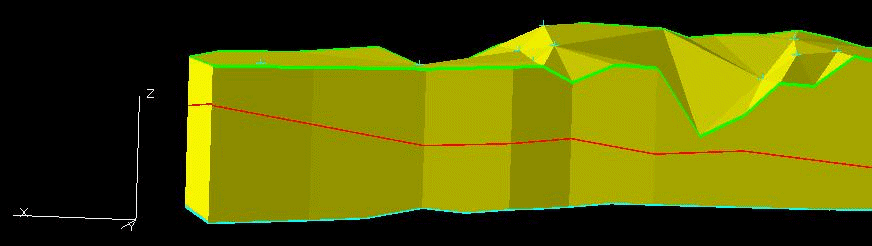
Figure 5: Choppy Back and Sill Polygons
Solution
This problem is generally due to insufficient and/or conflicting elevations of data points on the top or bottom of the as-built. View the data and decide which points are either in error or can be removed. In some cases, additional points will have to be added. The Build 3D Drive option works best when the survey data is somewhat centred, following the as-built wall/rib lines. Because the polygons that are generated by the Build 3D Drive option use elevations projected from the survey data at the top or bottom of the as-built, the elevations of the points in the polygons may contain a blend of elevations that translate into inaccuracies.
This solution to this problem is somewhat iterative. After creating the first as-built triangulation and polygons, visually identify areas that are not correct. Remove survey data that isn't necessary (i.e., other nearby points that have the same elevation, multiple points from left to right across the back, etc.) using the Design > Point Edit > Delete option. After removing some of these points, rerun the Build 3D Drive option. The corners should look better.
In some instances there is a lack of data, for example, at the end of a crosscut. Add a few extra points to the roof/back and/or floor/sill as needed. Make sure that the data you add is coalesced into the other data. You can use the Design > Object Edit > Coalesce option for this. After adding in the data, rerun the Build 3D Drive option.
The Generate option is used to create the survey data from an existing as-built triangulation, but you find out that the wall/rib polygon is broken into multiple pieces or objects, rendering that data unusable by the Build 3D Drive option.
Solution
It is a good practice to change the colour(s) of the wall/rib polygon using the Design > Attribute Edit > Graphics option. The entire polygon should be of one colour. If it isn't one object, the point where one line ends and another starts will be clearly defined by the contrast in colour. The cause of this problem is usually due to an anomaly in the triangulation that was used by the Generate option.
In Figure 6, the bevel portion of the triangulation is missing at one corner, which makes Generate restart drawing the polygon, thus making the new polygon or multiple line segments.
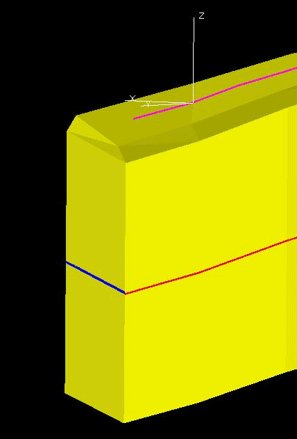
Figure 6: The bevel portion of the triangulation is missing at one corner.

