Create Solid
The Create Solid option allows to create triangulations (both solids and surfaces) that cover and adhere to the underground survey scans passed in as input. The underground scans need to be placed in a single layer in a design database. They comprise open and closed polylines that define the floor, wall, backs, and shoulders of the underground mine tunnels. They also have optional attribute and property information like group names that define which part (floor, wall, backs, etc.) of the underground mine they belong to and determine what the final triangulation solid/surface shape looks like.
Instructions
- Select Survey menu
- Select UG Survey submenu
- Select Create Solid option
The following panel shows up.
Open Specification
Specification file
Enter, or select from the drop-down list, the name of the specification file (.spec) containing the layers to be triangulated. The drop-down list contains all of the .spec files in the current working directory. Click Browse to select a file from another location.
To create a new file, enter the file name and file extension.
Solid ID
This is a list of panel parameter specs that define the final values of each element. This list of Solid ID definitions is based on the specification file selected. These can be added to, deleted, and modified using the standard spec widget controls.
Creation tab
Output files
Triangulation Directory
Select a directory in which all of the output triangulations will be saved. Choose one from the drop-down or browse to locate a different directory. Leaving this field blank will save the output files to the current directory.
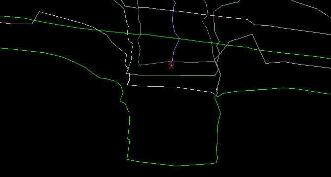
The checkboxes, which are used to select part of the underground scans, specify what parts will be created and saved as output triangulations.
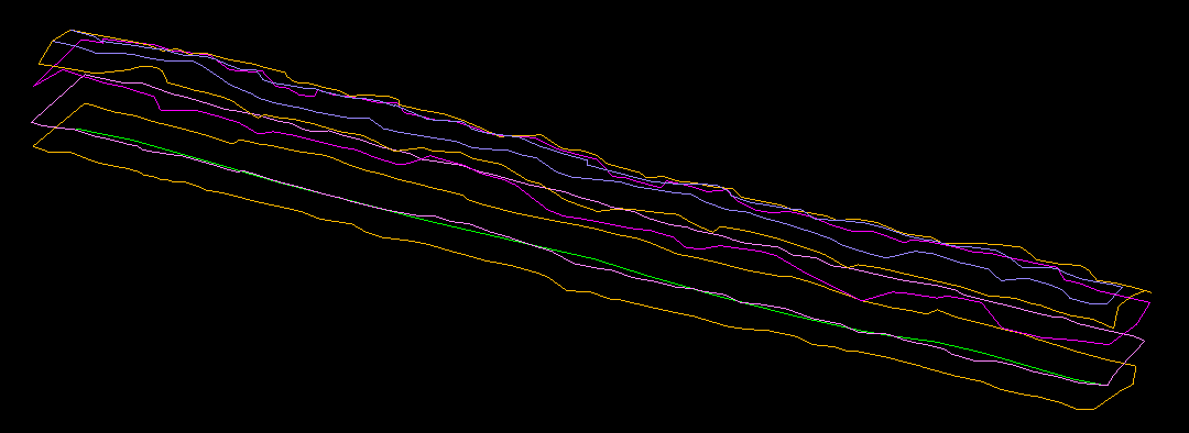
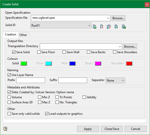
Figure 1: Underground Design Scans
Save Solid
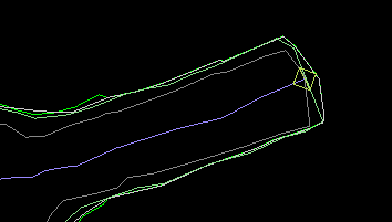
Select this to create one whole closed solid triangulation, which is the union of floor, wall, backs, and shoulders triangulations.
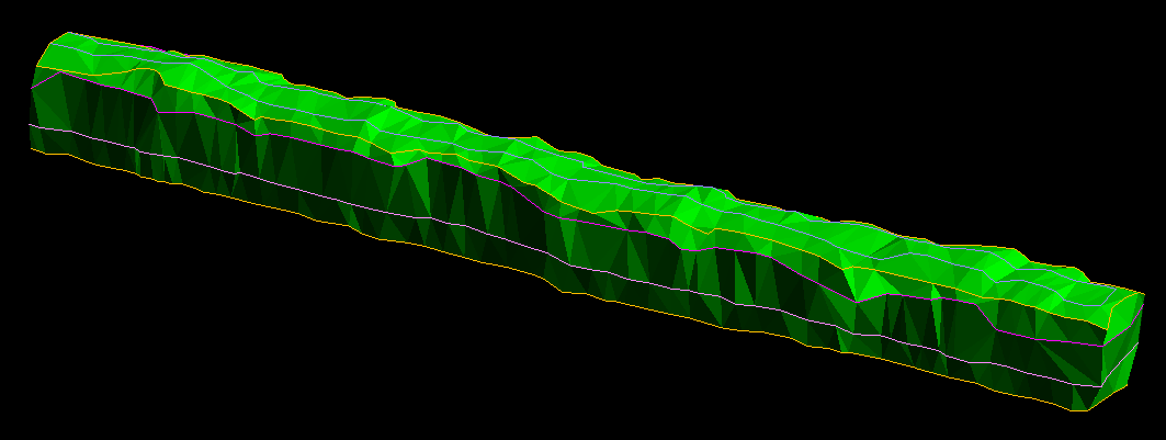
Figure 2: Resultant solid
Save Floor
Select this to create triangulation surface from the floor strings. The floor strings are situated at the lowest elevation level.
Note: that the open polyline(s) also take part in the creation of the triangulations. The triangulation surface has to adhere to the polylines where each point from the polyline ends up lying on the triangulation surface.
Figure 3: Resultant floor
Save Wall
Select this to create triangulation surface between the main floor polygon and main roof polygon.
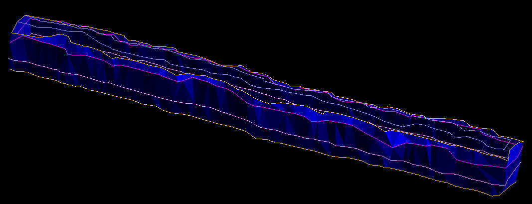
Figure 4: Resultant wall
Save Backs
Select this to create triangulation surface from the roof strings. The back strings (also called roof strings) are situated at the highest elevation level.
Note: that the open polyline(s) also take part in the creation of the triangulation. The triangulation surface has to adhere to the polyline where each point from the polyline ends up lying on the triangulation surface.
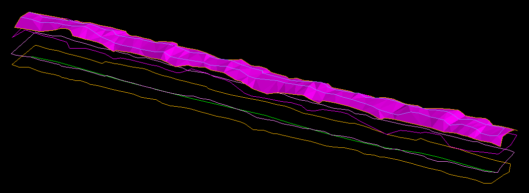
Figure 5: Resultant backs
Save Shoulders
Select this to create triangulation surface from the shoulder strings. Shoulder strings are located relatively below the elevation of the backs.
Colours
This option allows to setup the colours of the output triangulations.
Naming
These set of controls allow to attribute the filenames of the output triangulations.
A start-name is always added into the final filename for all triangulations. When creating the Save Solid triangulation, the literal “solid” is added at the start of the filename. Similarly when creating the Save Floor triangulations, the literal “floor” will be added and this naming scheme will be applied to the rest of the triangulations.
Use Layer Name
Selecting this option adds on the layer name where the design data came from after the start-name.
The Prefix and Suffix fields allow the user to enter a custom name which will be added to the beginning and end of the triangulation filenames respectively.
The Separator selector allows the user to select a character which will be put in the filename straight after the prefix (if there is a prefix at all) and straight before the suffix (if there is a suffix at all). It will also be put straight after the start-name (if there is at least one of these selected: prefix, suffix or layer name).
A template for the final name is as follows (curly brackets denote optional entry):
[START_NAME]{SEPARATOR}{PREFIX}{SEPARATOR}{LAYER_NAME}{SEPARATOR}{SUFFIX}.00t
Metadata and Attributes
These options allow the user to embed additional information and properties about the triangulation to its attributes.
Other
If the Save only valid solids checkbox is selected, the triangulation is saved given that the triangulation does not have crossing triangles and that all of the triangles have consistent direction. This applies to all the surfaces in all directions of all of the triangles in the plan. For solids, all of the triangle directions are same irrespective of whether you are looking at the triangle from the outside of the solid or inside.
If the Load outputs to graphics checkbox is enabled, the option loads all of the created triangulations on the screen.
Other tab
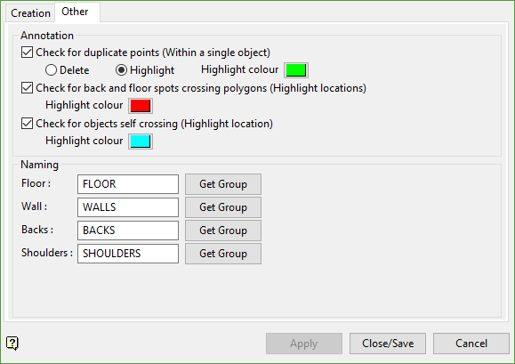
Annotation
This part of the panel allows the user to check for the validity of the input data. All of the checks are performed in plan.
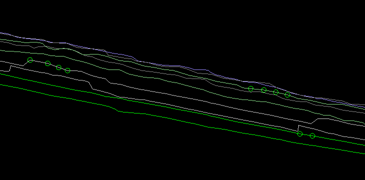
Check for duplicate points
The option checks if there are duplicate points within a single object. The user can either choose to remove the duplicate points or just annotate them on the screen. The check will be performed during the creation of the triangulations and a screen-aligned circle will be drawn around the points that are duplicated. The colour of the circle can be adjusted from the colour selector.
Check for back and floor spots crossing polygons
The option checks if there are crossing strings within the back and floor string set. The check will be performed during the creation of the triangulations and a screen-aligned cross will be drawn on the point of intersection between the two segments in question. The colour of the cross can be adjusted from the colour selector.
Check for objects self crossing
The option checks if there are objects that self-intersect. The check will be performed during the creation of the triangulations and a screen-aligned square will be drawn around the points of intersection between the two segments. The colour of the square can be adjusted from the colour selector.
Note: For all checks above, the option continues and produces the final result triangulations. However, the resultant triangulations might have in them some invalid areas. For example, if there are two different strings which intersect at a point, the triangulation surface on the point of intersection and in the neighbourhood around that point might have invalid elevation, or elevation that does not reflect the scans correctly. This is because for a single 2D XY plan value, there is more than one elevation value.
Along with the above checks, the option also detects multiple objects. If duplicate geometric objects are encountered, the creation of the triangulation is halted and user is prompted to delete the duplicate objects in order to continue.
Naming
This part of the panel allows user to modify the name that identifies which part of the underground survey scan the strings belong to. Usually strings that come in from underground scans have group names that specify the level-location within the underground structure. If, for example, a string is part of the floor structure, the design object representing that string will have its object name set to “FLOOR” (usually). We can also choose a different name, which allows us to get that particular name from the object’s group property.
The text boxes for each part of the underground are editable. That is the user can enter any name to be used as the new identifier. This identifier will be used to match each object’s group name and determine whether an object is part of the underground floor, backs or shoulders.
Clicking on the Get Group buttons shifts control back to the screen to query the user to select one object from the screen. Once the object is selected, its group name will be looked up and that will be stored as the new identifier name.
The group name is used to determine which part of the underground scan the string came from i.e. whether the string came from wall, floor, roof, etc.
After all the parameters have been configured, click Close/Save button. This saves the current selected parameters on the panel to the selected Solid ID in the specification file and close the panel.
To apply the option and produce the final triangulations, click the Apply button. This prompts to select the layer where the objects that will be processed are located. After that another selection has to be made in order to retrieve a closed polygon. This closed polygon acts as a main base polygon and all strings outside of it (per level i.e. for each part of the scan floor, roof, etc.) are ignored and do not take any part in creating the output triangulations. The main closed polygon also defines the boundary of the triangulations and all closed polygons inside them form holes or pillars in the final triangulations. There are usually two main polygons in one set of strings to triangulate but there can be more depending on the input scan. There has to be at least two closed main polygons in order for the triangulation creation to succeed.
The creation of the triangulations is performed by grouping each string into the floors, backs, and shoulders parts of the underground structure. A heuristic algorithm is performed to analyse the strings and determine whether a string should be included as part of the triangulation. The algorithm will also group closed strings based upon their plan location and effective size. This is performed in order to have a list of strings that have to be triangulated together in a top-down fashion, for example when creating the wall part of the solid.
A string can also be determined to be an outlier and therefore excluded from processing when creating the output triangulations.
Example: An example of an outlier string could be an open string that lies approximately halfway between the floor and roof. If it is an outlier, i.e. the heuristic deems it to be too far away from both the floor and roof set, the string is ignored. Upon successful completion of creating the triangulations, the outlier strings are labelled on the screen to highlight the fact.

