Over/Under Break
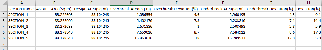
Use this option to compare the UG design to the as-built UG survey solid based in sections. The calculation for each section includes the design area, the actual area, the overbreak area, the underbreak area, and deviation percentage.
Instructions
On the Survey menu, point to UG Survey, then click Over/Under Break.
Steps
-
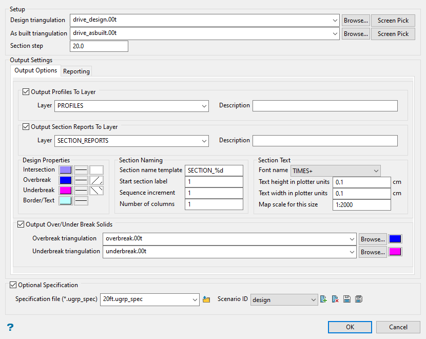
Select the Design triangulation and As built triangulation.
You can do this by using the drop-down lists, browsing for them in the Explorer by click the Browse button, or selecting them from the screen by clicking the Screen Pick button.
The design triangulation is the 3D solid that was created using the CAD tools. This is the predicted shape of the drive or stope.
The as-built triangulation is the 3D solid that was created from information gathered from the survey scans of the drive or stope.
-
Enter the distance between each section profile into Section step.
-
Select at least one output option found on either the Output Options tab or the Reporting tab.
 Output Options tab
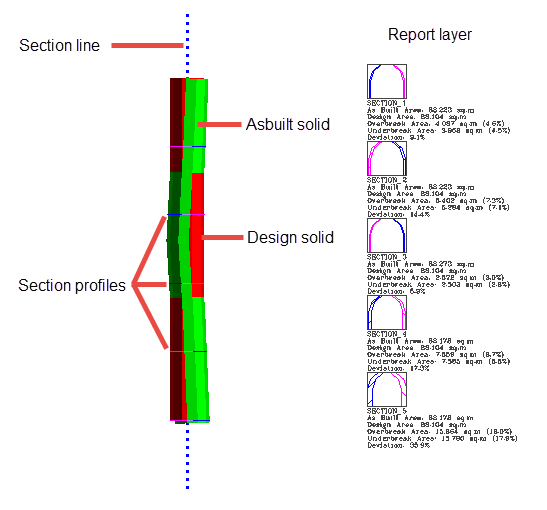
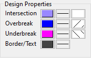
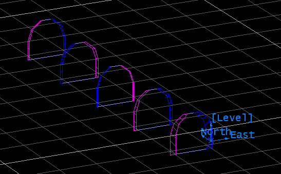
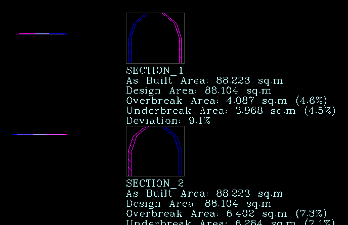
Output Profiles To Layer - This will create a single layer of all section slice profiles showing the overbreak and underbreak found at each section step. The colours designating each area are selected in Design Properties.
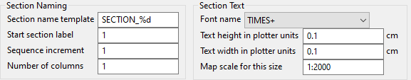
Output Section Reports To Layer - This will create a layer reporting the results of each section's design area, actual area (as built), overbreak area, underbreak area, and deviation percentage. The text properties are selected by using the Section Naming and Section Text inputs.
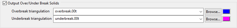
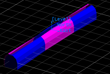
Output Over/Under Break Solids - This will produce two solids, one for overbreak, and one for underbreak. Enter a name for each solid and select a colour.
Note: If you decide to use the name of an existing solid, you will be ask to confirm overwriting it with a new solid.
 Reporting tab
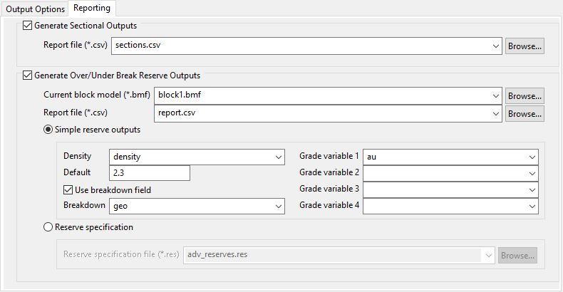
Generate Sectional Outputs - This will produce a CSV file reporting the results for each sectional profile.
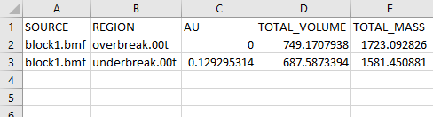
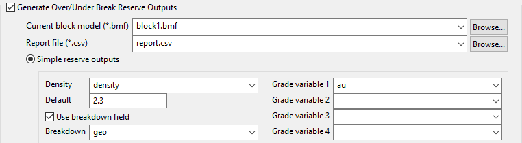
Generate Over/Under Break Reserve Outputs - This will produce a CSV file reporting the reserves found within the overbreak and underbreak solids.
Note: This option will be enabled only if you have selected the option to create overbreak and underbreak solids found on the Output Options tab.
You can calculate the reserves by choosing either Simple reserve outputs or Reserve specification.
-
Simple reserve outputs - This option will allow you to set up basic estimation parameters using the inputs on this panel.
-
Reserve specification - This option will allow you to use an existing (
.res) file, such as one created with the Advanced Reserve Editor.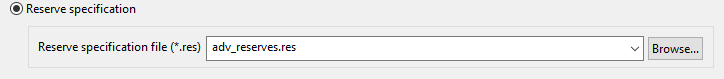
-
-
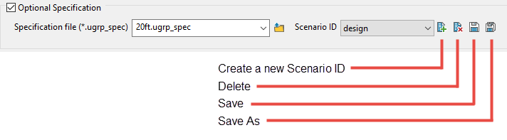
Enter a name for the Specification file.
This is recommended if you want to preserve the settings used in the panel.
-
Click OK.

