Stope Framework
Use Stope Framework to define the stope framework and stope orientation plane. Additionally, you must specify the size and orientation of the framework.
Requirements
A block model must be selected from the Open Specification page.
Instructions
On the Underground menu, point to Analyse, click Stope Optimiser, and then select Stope Framework from the tree menu on the left to display the Stope Framework panel.
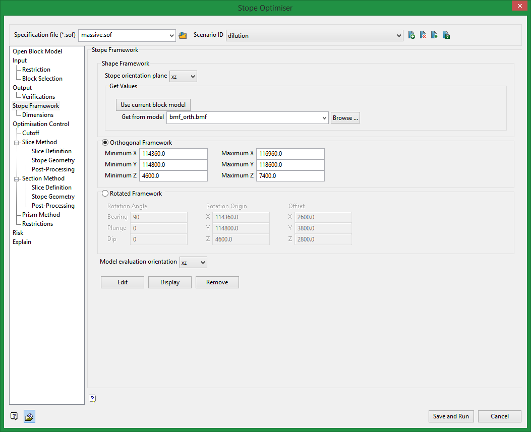
Shape Framework
Stope orientation plane
Select the desired orientation plane, xy, xz, yx, or yz.
The selection made here will determine which of the step extent fields is automatically calculated: The X step is done if you choose yz; the Y step if you choose xz; or the Z step if you choose xy or yx.
Note: For the section method (defined on the Open Specification panel) you can only use vertical stope orientation planes (xz or yz). Additionally, you do not need to specify the Z step; this will be optimised in section method and configured on the section method panel.
Get Values
This allows you get stope framework extents from an existing model. This includes block models or triangulation models.
Use current block model
Select this option to populate the minimum and maximum extents from the currently loaded block model. It the block model is rotated it will select a rotated stope framework and populate orientation and extents appropriately.
Get from model
If you do not want to use the current block model to populate the minimum and maximum extents, you can select a block model or triangulation from the drop-down that you want to use instead. All available block models and triangulation from the current working directory are displayed. Click Browse to select a file from another location.
The calculated Step field (determined from the selection in Stope orientation plane) will automatically be updated based on the information from the selected block model. The other two Step fields will not be populated. These must be filled out manually in accordance with your desired stope sizes.
Choose between Orthogonal and Rotated Framework
One of two types of frameworks can be specified; orthogonal and rotated. An orthogonal framework is defined by a minimum and maximum X, Y and Z. A rotated framework is defined by an origin, orientation and offsets in respective directions.
The orientation of the framework will affect the orientation of the output stopes. Additionally, the interaction between stope framework and block model orientation will affect processing time.
Orthogonal Framework
Minimum X
Enter the minimum value of X (east) for the stope framework.
Maximum X
Enter the maximum value of X (east) for the stope framework.
Minimum Y
Enter the minimum value of Y (north) for the stope framework.
Maximum Y
Enter the maximum value of Y (north) for the stope framework.
Minimum Z
Enter the minimum value of Z for the stope framework.
Maximum Z
Enter the maximum value of Z for the stope framework.
Rotated Framework
Rotations of the input block model and of the stope shape framework are optional and independent. Keep in mind that the orientation of the framework affects the orientation of the output stopes.
Rotation Angle
Use this section to enter the rotational values: bearing, plunge, and dip. Click on the Edit button to display the transform object and manipulate the bearing, plunge, and dip values interactively.
Bearing
Enter the desired Bearing for the stope framework. Note that is it the bearing of the X-axis. This is important to understand in order to choose the proper stope orientation plane.
Plunge
Enter the desired Plunge for the framework.
Dip
Enter the desired Dip value for the framework.
Rotation Origin
Use this section to enter the origin of the framework. Rotation of the framework will be applied about this point.
Offset
Indicate the extents of the framework by specifying the offsets in the relative X, Y and Z directions.
Model evaluation orientation
Select the model evaluation orientation from the drop down. In most cases you will select the model evaluation orientation to match the stope orientation plane. The model evaluation orientation defines the plane used for Discretisation. Model Discretisation is further defined by the user on the Optimization Control panel.
For interactive framework tools, select one of the following options:
Edit
Click to display the Transform Object panel, where you can enter new values or manipulate a graphic representation of the framework to customise the extents.
Display
Click to draw a box using the extents values entered and view the stope framework. Use the Shift key in combination with the left mouse button to reposition the centre of rotation.
Remove
Click to clear the stope framework from the Vulcan screen.
Related Topics
Section Method Slice Definition
Section Method Post Processing

