Coordinate Systems
The following table describes the tools in the Coordinate Systems section of the Edit tab.
| Tool | Description |
| Convert | Converts objects which are in one coordinate system to another coordinate system. |
| Define | Defines an initial coordinate system to the selected object. |
| Tools |
Used to interact with one or more coordinate systems. Tools include:
|
Convert
To convert coordinate systems:
-
Select the object to convert.
-
Go to Edit > Coordinate Systems > Convert.

-
Specify a coordinate system automatically by picking another object and transferring. To transfer a coordinate system automatically from another object, give focus to the Specify system by picking object field, then either:
-
Middle-click and drag the reference object into the field.
-
Left-click the reference object in the view window.
-
-
Check the 2D transform checkbox if the Z coordinates of the selected points are to be maintained.
-
Click OK or Apply to convert the selected objects into a new system.
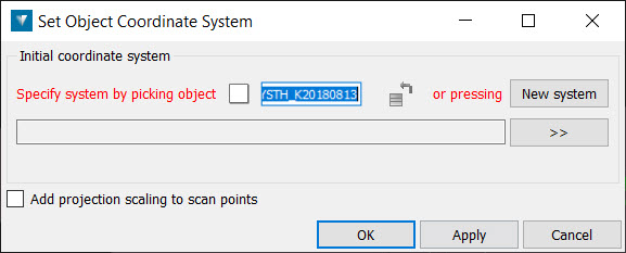
Define
To define a coordinate system:
-
Select the required object.
-
Go to Edit > Coordinate Systems >Define.
-
Specify a coordinate system either by automatically transferring the coordinate system applied to another object. To transfer a coordinate system automatically from another object, give focus to the Specify system by picking object field, then either:
-
Middle-click and drag the reference object into the field.
-
Left-click the reference object in the view window.
-
-
Check the Add projection scaling to scan points checkbox if you want to apply projection scaling and distortion as if transforming from a geocentric coordinate system. This should only be used for raw laser scan data.
-
Click OK or Apply.
Tools
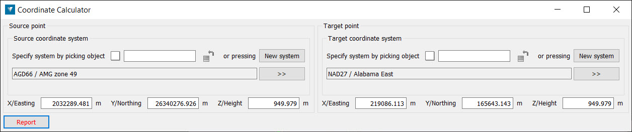
Calculator
The Coordinate calculator is used to report the position of a given point in any other coordinate system. For example, to show the latitude and longitude of a point with coordinates in a UTM grid.
To use the Coordinate calculator:
-
Go to Edit > Coordinate Systems > Tools > Calculator.
-
Define a coordinate system for the Source point either by transferring the coordinate system applied to another object, by clicking the New System button to access the Define system panel, or choosing a system that has been predefined in the Preferences tab. Note that the New System button is only available if predefined systems have not been established via the Preferences.
To transfer a coordinate system from another object, give focus to the Define system by picking object field, then either:
-
Middle-click and drag the reference object into the field.
-
Left-click the reference object in the View window.
-
-
Define a coordinate system for the Target point as for the Source system in step 2.
-
Left-click a point in the View window. The Source point and Target point coordinates will be displayed in the panel.
-
Click the Report button to display the results in the Report window.
Geodesic Distance
The geodesic distance is the shortest distance between two points on the surface of an ellipsoid. It can be thought of as the shortest distance one would have to travel between two points, at sea level, on the surface of the earth.

To calculate the geodesic distance:
-
Go to Edit > Coordinate Systems > Tools > Geodesic Distance. This will open a new panel.
-
Select Point A and Point B from points on an object. The objects must both have the same coordinate system defined, as it is the coordinate system's reference ellipsoid over which the geodesic distance is measured.
-
The coordinates of two points are reported in the panel along with the geodesic and Euclidean distances between the points. The Euclidean distance is the distance between the two points measured using the point's X and Y coordinates.
-
The scale is the ratio of the Euclidean to geodesic distances. This can be used as a measure of how accurate the map grid projection is in the vicinity of the points.
-
Click Report to write the distance information to the report window.
Geographic Graticule
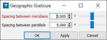
To create a geographic graticule:
-
Go to Edit > Coordinate Systems > Tools > Geographic Graticule. This will open a new panel.
-
Specify a spacing between Meridians (longitude) and Parallels (latitude).
-
Click OK or Apply to create the object.
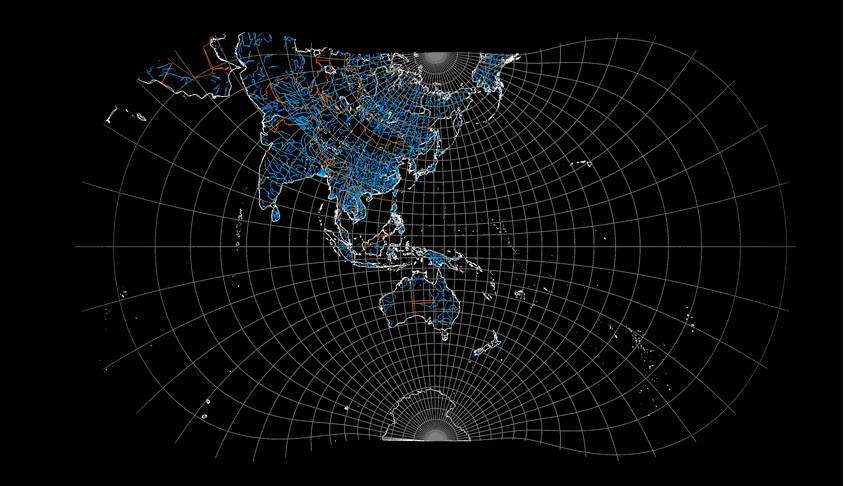
The image below shows a geographic graticule (in grey) which has been transformed from a geographic representation to WGS84 / UTM zone 54S using the Convert tool.
Visualise Geoid
Geoid files can be read into Eureka using geoid files of extension types .asc, .byn, .ggf or .gtx.
To select the required geoid, toggle the radio button to Select imported geoid and select the desired geoid from the drop-down menu.
