Step 5: Validate the Model
Model validation is an important part of the modelling process. Validation helps ensure that a model matches the source data and reflects the geological structures being modelled.
The trained human eye is very good at quickly identifying modelling results that don’t quite make geological sense. Perform visual checks on your model using a range of tools, including section mode, juxtaposition view, and filtering.
Vulcan GeologyCore also provides tools that run numeric checks that compare the modelled domains with the input domains.
Visual Checks
With so much data on the screen, it can be hard to make sense of what you’re looking at. Use the following tools to manage what you see in a view. Make sure you’re familiar with the ways of showing and hiding objects in the view.
Quick section and juxtaposition view
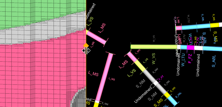
A convenient way to compare a model against the drillholes is to use juxtaposition view in combination with the section tool.
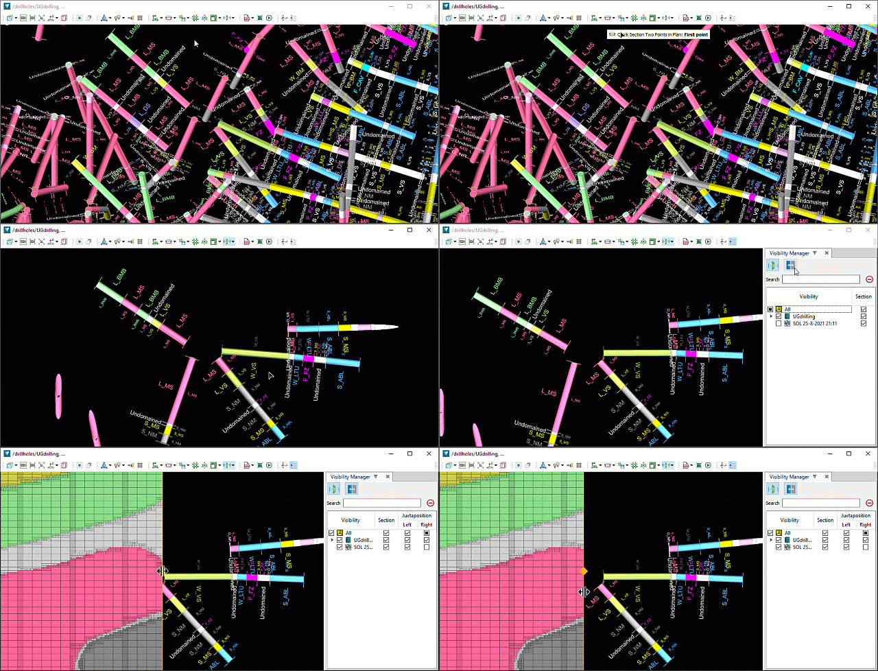
To do this, follow these steps:
-
Define a section plane.
-
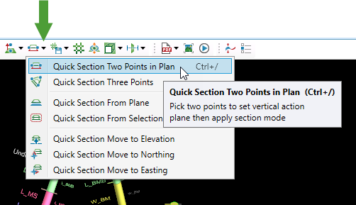
The quickest way to define a vertical section is use the Quick Section Two Points in Plan option, located in the Quick Section menu of the view window toolbar. The hotkey for this option is Ctrl+/. Pick two points in the view (on your drillholes or model surface) to define the vertical plane.
Tip: If you want to align the section to particular drillholes, but the model is obscuring the view, hide the model temporarily by holding down the H key to enter
 Hide mode, then click on the block model.
-
-
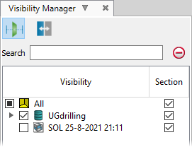
Turn on the Visibility Manager. To do this, either click
 in the view window toolbar, or press the V key. The visibility manager appears docked in the right-hand side of the view. Hide or show items loaded in the view by toggling the checkbox to the left of the item.
-
Click
 to toggle Juxtaposition view on.
 -
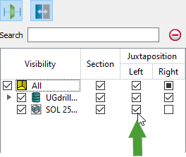
Make sure one of the Left or Right checkboxes under Juxtaposition for your model is selected.
-
Drag the orange slider in the view left or right to change its location in the view.
The normal view controls also still apply: Alt+click and drag to rotate, Alt+middle click and drag to pan, and Alt+right click and drag to zoom.
Block and point filtering
For block models, it is helpful to control the visibility of individual domains within the model. You can do this using the Point/Block Filter. The same tool can also be used to filter any attributed point data.

-
To filter a block model or point set by attribute, select the object and click
 Point/Block Filter. Alternatively, right-click on the object in a view window and navigate to Filter By > <Attribute> in the context menu.
The Filter by Attribute panel appears.
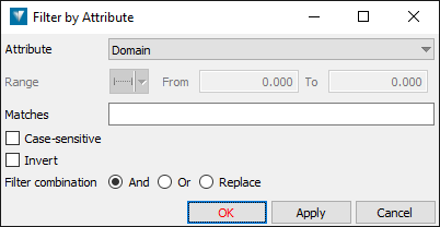
Configure the filter and click OK or Apply.

To filter a block model or point set by attribute:
-
Select the attribute you wish to filter by from the Attribute drop-down.
-
Specify the value or values you want to match.
-
If the attribute is continuous, Range will be active; enter the value range you wish to match.
-
If the attribute is discrete, Matches will be active; enter a string you wish to match.
You can use ‘*’ (multiple character) and ‘?’ (single character) wildcards.
Select Case-sensitive to match the string case-sensitively.
-
Select Invert to invert the sense of the match, i.e. show the blocks or points that fall outside the range or that do not match the given string.
-
-
From Filter combination, choose how the filter should be combined with any filter previously applied to the selected data:
- And—points or blocks matching the current filter AND the previous filter will be shown.
- Or—points or blocks matching the current filter OR the previous filter will be shown.
- Replace—the current filter will replace any previous filter applied.
-
-
To remove all filters, select the object and click
 Show All. Alternatively, right-click on the object in a view window and navigate to Filter By > Show All in the context menu.
Numeric Checks
Different kinds of numeric checks are available depending on the model type.
Solid Model Error Analysis
Solid model error analysis is a way of checking that the data used to generate a model lies inside or on the final model. It can be applied to any solid model, and as such is useful to check the output of vein or implicit modelling. Use the ![]() Solid Model Error Analysis tool to validate the model, or troubleshoot areas that may need additional control, a finer resolution, or more interpretive data.
Solid Model Error Analysis tool to validate the model, or troubleshoot areas that may need additional control, a finer resolution, or more interpretive data.
To perform solid model error analysis, follow these steps:
-
On the ribbon, navigate to Modelling > Post-Validation >
 Solid Model Error Analysis.
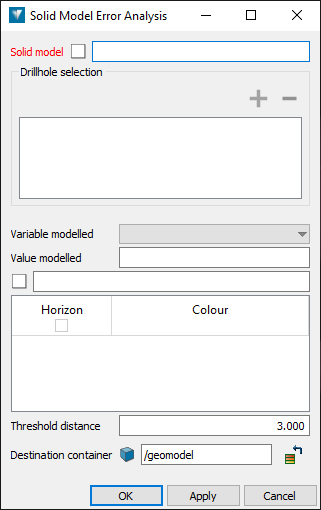
The Solid Model Error Analysis panel appears.
-
In the Solid model field, specify the solid model
 you wish to analyse.
 Expand for more details on how to fill out this field.
You need to supply a solid surface object
 in this field. There are three ways to do this:
-
Drag and drop the solid from the project explorer. Use the middle mouse button to preserve the current selection.
-
Click on the solid in a view window—making sure the field is active first (indicated by a red label).
-
Type the path to the object directly.
-
-
In the Drillhole selection list, specify the drillholes
 you want to compare the model against.
 Expand for more details on how to fill out this field.
This field requires a drillhole selection from a single database.
-
Add a drillhole database
 or drillhole
  subset to the list by making a selection in the project explorer and then clicking
  . Alternatively, drag and drop the drillhole database or selection directly from the project explorer into the drillhole list.
-
Remove an item by selecting it in the list and clicking
 .
.
-
-
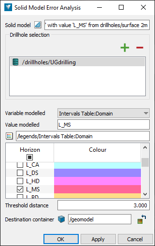
From the Variable modelled drop-down, select the table and field representing the variable that was modelled. If the variable is your drillhole domains, select Intervals Table:Domain.
-
Specify the value that was modelled. Either:
-
In the Value modelled field, enter the name of the value that was modelled.
-
If there is a compatible legend for the variable modelled, make sure it is specified under Legend. Then, select the checkbox for the value from the Horizon column.
-
-
In the Threshold distance field, specify a distance from the model beyond which a point is considered to be outside the model. This value should be greater than zero, since the nature of modelling means that many points may lie just outside the solid.
-
In Destination container, specify where the output point set should be stored.
-
Click OK or Apply.
The tool performs the analysis and displays a summary of the result in the report window.

If any points are found to lie outside the model beyond the specified threshold, they are saved to a point set in the specified container. To view the points, you can right-click on the object in the report summary, and select View “<object name>” or Send “<object name>” To from the context menu.
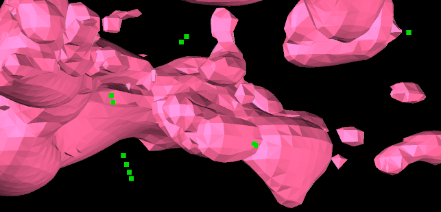
Tip: Can’t see the points easily? Press the + and - keys to increase and decrease the point size in the view.
Counts and Grade Statistics
If you have a block model generated by DomainMCF modelling, you can compare it against the input drillholes by generating counts and grade statistics.
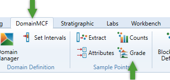
To generate a counts chart, select the block model and then on the ribbon, navigate to DomainMCF > Sample Points > ![]() Counts.
Counts.
To generate a grade chart, select the block model and then on the ribbon, navigate to DomainMCF > Sample Points > ![]() Grade.
Grade.
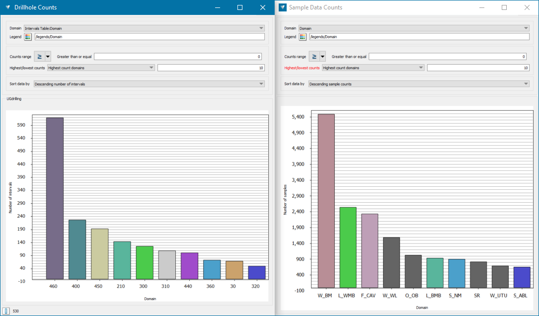
Generate the corresponding charts on the drillholes (see Step 2: Validate Drillhole Data for how to do this), and then compare them side-by-side by undocking the chart windows.
|
Step 6: Publish the Model
|