Tutorial #1: PointStudio workflow examples
PointStudio users commonly take scan data and perform a series of operations on this data to produce a surface. Manually, this would be achieved in PointStudio by running a set of operations on the data in sequence and inputting parameters as you go. The sequence might typically involve filtering the scan, modelling the surface and then despiking the surface. The examples below are step-by-step guides on how to take such a series of PointStudio operations and turn them into an automated workflow. Once the workflow is created, it can be run on a selected scan. The operations comprising the workflow will run with the parameters defined by the workflow without requiring any further input from the user.
To run these examples, you will need to download the example scan data located here:
Example workflow #1
The following operations will be run in sequence:
-
Filter Range — to remove a vehicle present in vehicle mounted scans.
-
Filter by Topography — to remove points above other points
-
Model Topographic Surface
-
Despike resulting surface
To create and run this workflow:
-
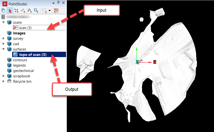
Import the example scan into Maptek PointStudio.
-
Initialise a new workflow by opening the Workflow Editor.

-
-
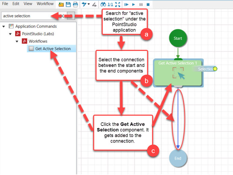
Search for PointStudio’s Active Selection component in the Toolbox Filter.
-
Click the connection between the Start and the End node.
-
Then, click the Active Selection component from the Toolbox. The component will be added between the Start and End nodes in the Editing Area.
-
-
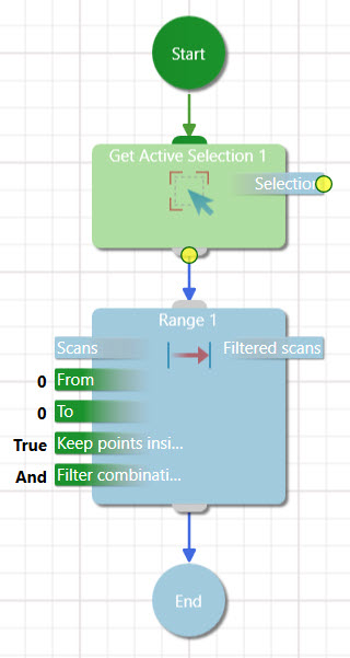
Using the same procedure as above, navigate to PointStudio > Position and Filter > Filters > Range in the Toolbox Filter, and add the component between the Active Selection component and End node.
-
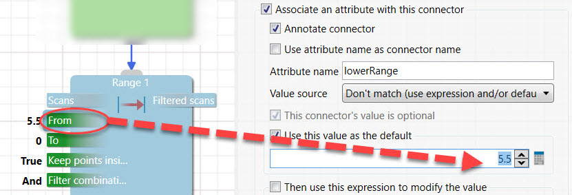
Change the From input connector to value 5.5 by selecting the connector to open the right-hand panel. Change the To input connector to value 200 using the same method.

-
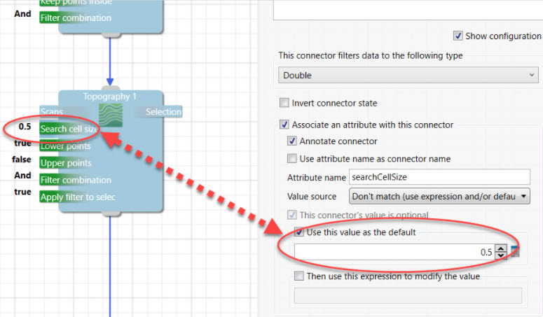
Add a Pointstudio > Position & Filter > Topography component. Set the search cell size to 0.5.
-
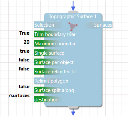
Add a Create > Topography Surface component. Set default values for the trim boundary triangles input connector to True, the maximum boundary edge length to 20 and the destinations folder to /surfaces. Delete the Relimit polygon input connector by selecting it and clicking the Delete key.
-
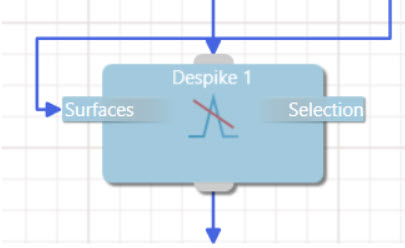
Locate the Despike component (PointStudio > Edit > Despike) and add it to the workflow. Delete the Context object input connector by selecting it and clicking the Delete key.
-
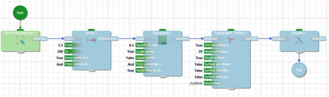
The final step before running the workflow is to connect all components from start to end to indicate the flow of data. This is performed by clicking the output connector and dragging the connection to the input connector of the upcoming component. The final workflow should look like this:
-
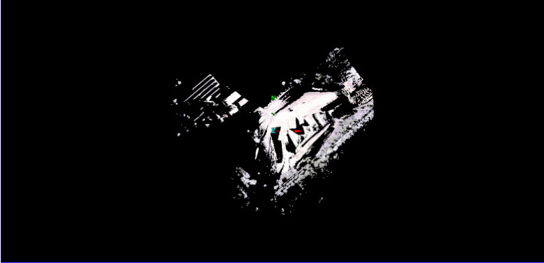
Select the scan in the Data Explorer and run the workflow. A filtered topographical surface should be created. If not, go back through the example and make sure that all components and connectors are correctly configured.
Example workflow #2
The next workflow is a contrived variation of the previous workflow but is designed so that users can learn how to use the following tools:
-
A Message Dialog Box, which allows for real-time user interaction.
-
A Custom Panel, entirely designed by the user.
-
An On-any waypoint, where two separate paths converge to the same execution step.
To create this workflow:
-
Download the scan again and recreate or reuse the workflow in example #1 above.
-
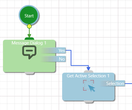
Add a Message Dialog Box just after the Start component. Set its response type to YesNo and the Message content to "Would you like to execute path A (Yes) or path B (No)?".
-
Join the Yes output connector to the top input connector of the Get Active Selection component.
-
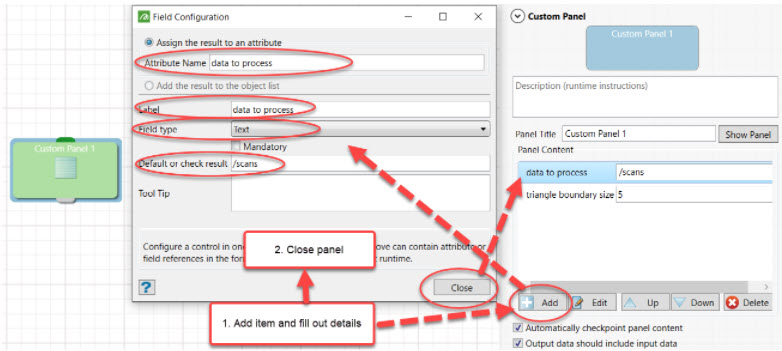
Add a custom panel component to the Editing Area. Add two panel content items: data to process (field type = text) and boundary triangle size (field type = numeric). The data to process item should be set to the text value "/scans" (you want the software to access the scans folder) and the boundary triangle size should be set to the value 5.
-
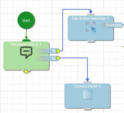
Connect the No connector from the Message Dialog Box to the Custom Panel.
-
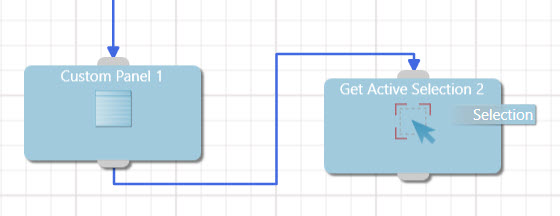
Copy and paste the Active Selection component from the left hand side workflow and connect it to the Custom Panel as shown below.
-
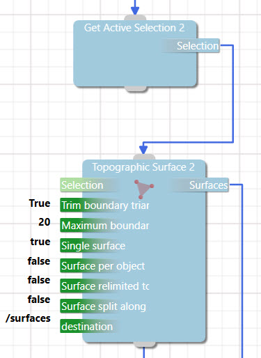
Copy and paste the Topography Surface component from the left hand side workflow to the right as shown below.
-
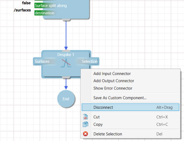
Scroll down to the Despike component and disconnect the component from the workflow using the right-click context menu.
-
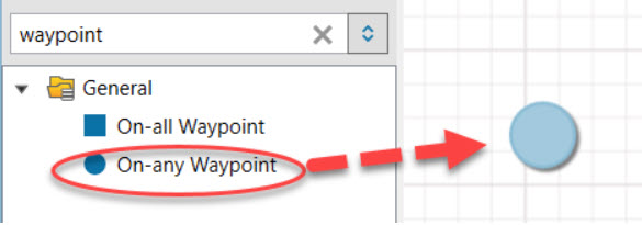
Search for "waypoint" in the search box of the Component Palette, and add the On-any waypoint to the Editing Area. This waypoint is used to make the two pathways converge on a shared component: the Despike component. In other words, whatever pathway the user might choose, because of the use of an on-any waypoint, the despike operation will always be performed.
-
Join all inputs and output connectors so that the final output looks like the workflow in the image below:
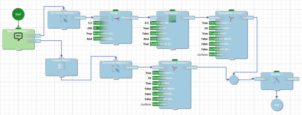
-
Run the workflow. A dialog will prompt you to choose a pathway. Regardless of the pathway taken, the following surface (or something similar) should be created.