Action
Source file: charging-action.htm
The Action group of the Charging ribbon contains tools to create charge and tie-up sheets.

 Create Charge Sheet
A charge sheet is an interface created to record and store charge data for a selection of holes. Charge sheets are created using the desktop application and then accessed on the tablet application against which operators can enter data.
To create a charge sheet, follow these steps:
- Select all holes from the blast via the project explorer, or a subset of holes from a blast loaded in the view window. The blast needs to be published (for information regarding publishing blasts, see Publishing a Blast).
- Go to Charging ribbon > Action group >
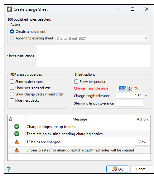
 Create Charge Sheet to open the Create Charge Sheet panel.
 -
Specify whether to create a new sheet or append to existing sheet by selecting the corresponding radio button.
-
Enter any Sheet instructions. These instructions will be shown on the cover page of the printable charge sheet.
- Select the options you would like to add to either a physical sheet (PDF sheet properties) or a virtual sheet (accessed on the tablet):
- Charge mass tolerance (%). The maximum tolerated difference between the planned charge mass and the loaded charge mass.
- Charge length tolerance (metres). The maximum tolerated difference between the planned charge length and the loaded charge length.
- Stemming length tolerance (metres). The maximum tolerated difference between the planned stemming length and loaded stemming length.
- Click OK.
- The charge sheet will appear under the Sheets container belonging to the affected blast. A PDF version of the newly created blank charge sheet will be displayed on the screen. Any blast properties that have been marked as Area of mine will be displayed on the cover page alongside the sheet instructions. A summary of total blast product usage will also be shown on the cover page of the charge sheet.
You can also create a new sheet by right-clicking the Sheets container of the corresponding blast on the explorer panel
and selecting ![]() New Charge Sheet....
New Charge Sheet....
 Design Tie-up Sheet
The Design Tie-up Sheet tool allows you to design and export a tie-up sheet.
To design a tie-up sheet, follow these steps:
-
Select a tie-up in the project explorer or view window.
If you do not select a tie-up, this tool will be greyed out in the ribbon.
-
On the Charging ribbon, in the Action group, select
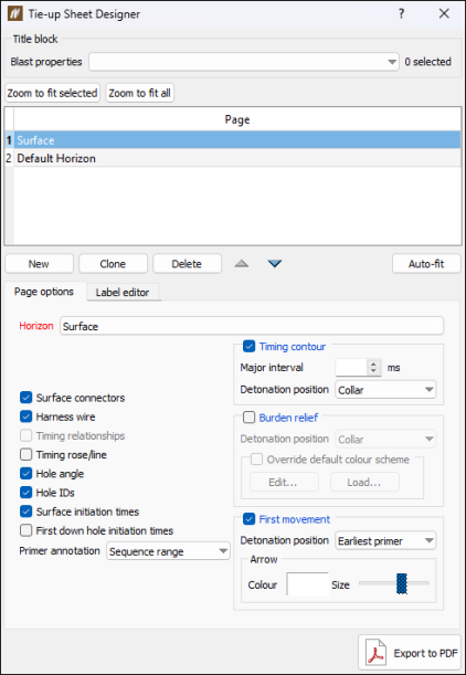
 Design Tie-up Sheet. The Tie-up Sheet Designer panel will appear.
-
For a new tie-up sheet design, add pages to the Page table by clicking the New button. For information on configuring pages in this panel, see step 7.
-
For an unpublished tie-up, select the checkboxes of the blast properties you wish to add to the page from the Blast properties drop-down.
-
BlastLogic will display the page you select from the Page table in the view window.
Choose one of the following ways to toggle between an active and inactive page:
- By selecting an inactive page in the Page table.
- By middle-mouse clicking on the inactive page in the view window.
-
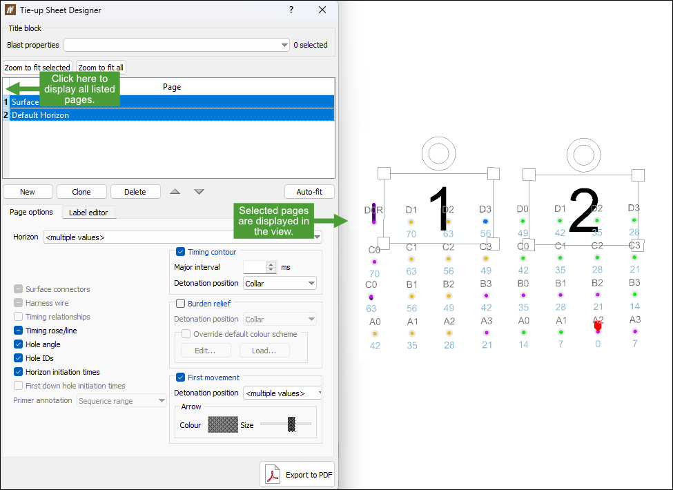
To display several pages at the same time, press Ctrl and select pages you want to include in your view from the Page table.
Tip: When you select two pages while pressing Shift, all pages between these two pages will be selected.
-
To display all listed pages, click the top-left corner of the Page table.
-
To move a page in your view, middle-mouse click the page and place it in the desired location.
-
To change the size of a page in your view, middle-mouse click on one of its corners and drag it to set the required size.
-
To rotate a page in your view, middle-mouse click on the circle outline that is visible above the page boarder. The circle will become red, and the boarder of the page will turn to blue colour. Rotate the page outline while holding the middle mouse button to set the required angle.
-
You can move, rotate or change the size of several pages at once by selecting them in the Page table while pressing Shift or Ctrl, and then performing the required operations as described above.
-
Optionally, use the following options:
-
Add more pages by clicking New. BlastLogic will add a new page to the Page table.
-
Clone a page by selecting the page and clicking Clone. BlastLogic will add the cloned page to the Page table with the naming convention Copy of <original page name>.
-
Delete a page by selecting the page and clicking Delete.
-
-
Interact with the following panel tabs:
-
Page options
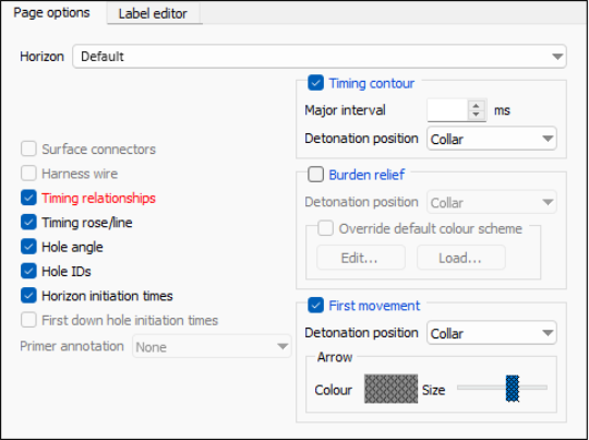
This subtab contains options that allow you to edit the selected page.Horizon: Surface Horizon: Default 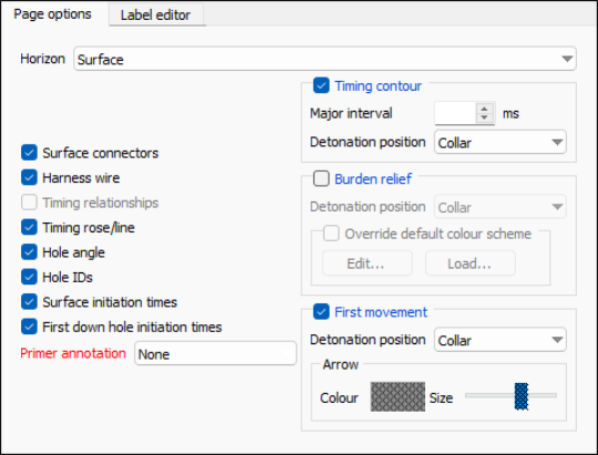
-
To set the horizon for the page, select either Surface or a horizon from the Horizon drop-down.
Note
The list of the available horizons will depend on the settings you have applied in the Edit Horizons window (Tie-up Editor > Elec tab > Edit horizons...).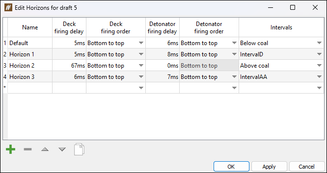
See timing horizons in Create Tie-up Design for more information. - To add tie-up features to the selected page, select the required checkboxes on the left side of the panel.
Note: Certain options may be greyed out depending on the option you select from the Horizon drop-down.
- To set the primer annotation, select the desired annotation option from the Primer annotation drop-down.
-
To display the timing contour on the selected page, select the Timing contour checkbox. You can then enter the desired interval and detonation position into the Major interval field and Detonation position drop-down respectively.
-
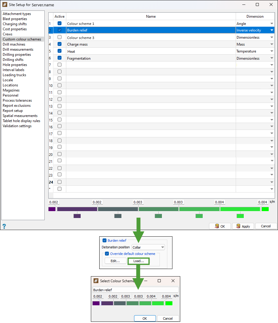
To display the burden relief on the selected page, select the Burden relief checkbox. You can customise the way burden relief is displayed by selecting the required option from the Detonation position drop-down and changing the colour scheme by selecting the Override default colour scheme checkbox. See Burden Relief Surface for more information.
 Expand for more information on setting colour scheme.
The Override default colour scheme checkbox allows you to define the way the burden relief is displayed in your view by the following buttons:
Edit... When clicked, the following dialog window appears:
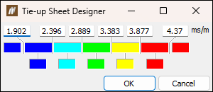
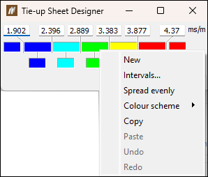
You can enter the values for each interval manually, or right-click on a colour field to customise the interval scheme.
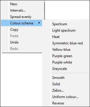
The options available for you to select in the context menu are:
-
New: Adds a new interval in the place that you have right-clicked on.
-
Intervals...: Allows you to specify the number and range of intervals in your colour scheme.

-
Spread evenly: Sets equal intervals for the colour scheme.
-
Colour scheme: Allows you to apply a predefined colour scheme and colour scheme effects.
-
Copy: Allows you to copy your colour scheme. You can then save it in the Custom Colour Schemes panel. See Burden Relief Surface for more information.
-
Paste: Allows you to paste previously copied colour scheme.
-
Undo: Cancels last performed operation.
-
Redo: Reverses the most recent change you have made using the Undo option.
Load... Allows you to load a colour scheme that you have saved in the Custom colour schemes panel (Home ribbon > Setup group >  Site). For this button to become active, you need to have a colour map with Inverse velocity dimension defined in the Custom colour schemes panel.
-
-
To display the direction that the rock is expected to move after detonation at each point, select the First movement checkbox. You can then enter a detonation position into the Detonation position drop-down. You can also customise the way the direction arrows will be displayed in your view by specifying their colour and size. See First Movement Diagram for more information.
-
-
Label editor
This subtab allows you to customise the labels of the selected page.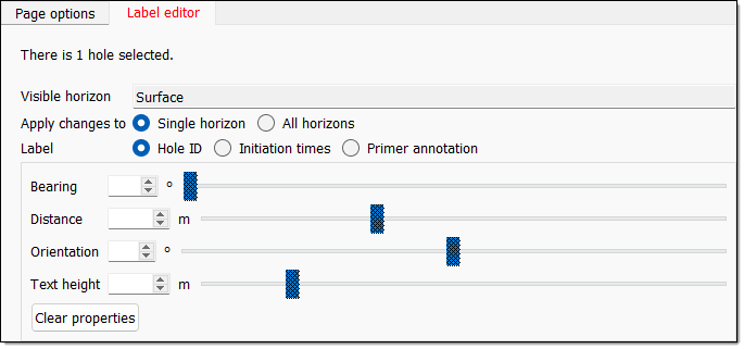
To apply your settings, follow these steps:
-
Select the desired holes in the view window.
-
Select the radio button of the horizon you wish to apply the changes to. You can select either Single horizon or All horizons.
-
Set the label you wish to give the selected holes. You can select from the following labels:
- Hole ID
- Initiation times
- Primer annotation
-
Use the following label option sliders or fields to edit the labels:
- Bearing
- Distance
- Orientation
- Text height
- Optionally, clear the set properties by selecting Clear properties.
-
-
-
Optionally, export the tie-up sheet by clicking Export to PDF. The file explorer will appear, allowing you to specify an export location. Click Save to confirm the export.
