Road Networks
Source file: howto-road-networks.htm
Road networks enable the software to calculate the time it takes to transport material from one point to another. A network consists of a number of edges and points. Both edges and points have attributes, e.g. rolling resistance and speed limit on edges and ending velocities on points.
Significant points on the road network can be flagged and identified as either sources or destinations. These are known as waypoints. To calculate the best route between a source and a destination, the next step is to create a link between them. Once this occurs, a path will be found or interpolated between those points.
To understand how Evolution calculates the best route, it would be helpful for you to understand how the software classifies segments of a pathway. While the images in this section refer to an Origin Solids setup, the same principles apply for an Origin Blocks or Epoch setup.
Road Network Components
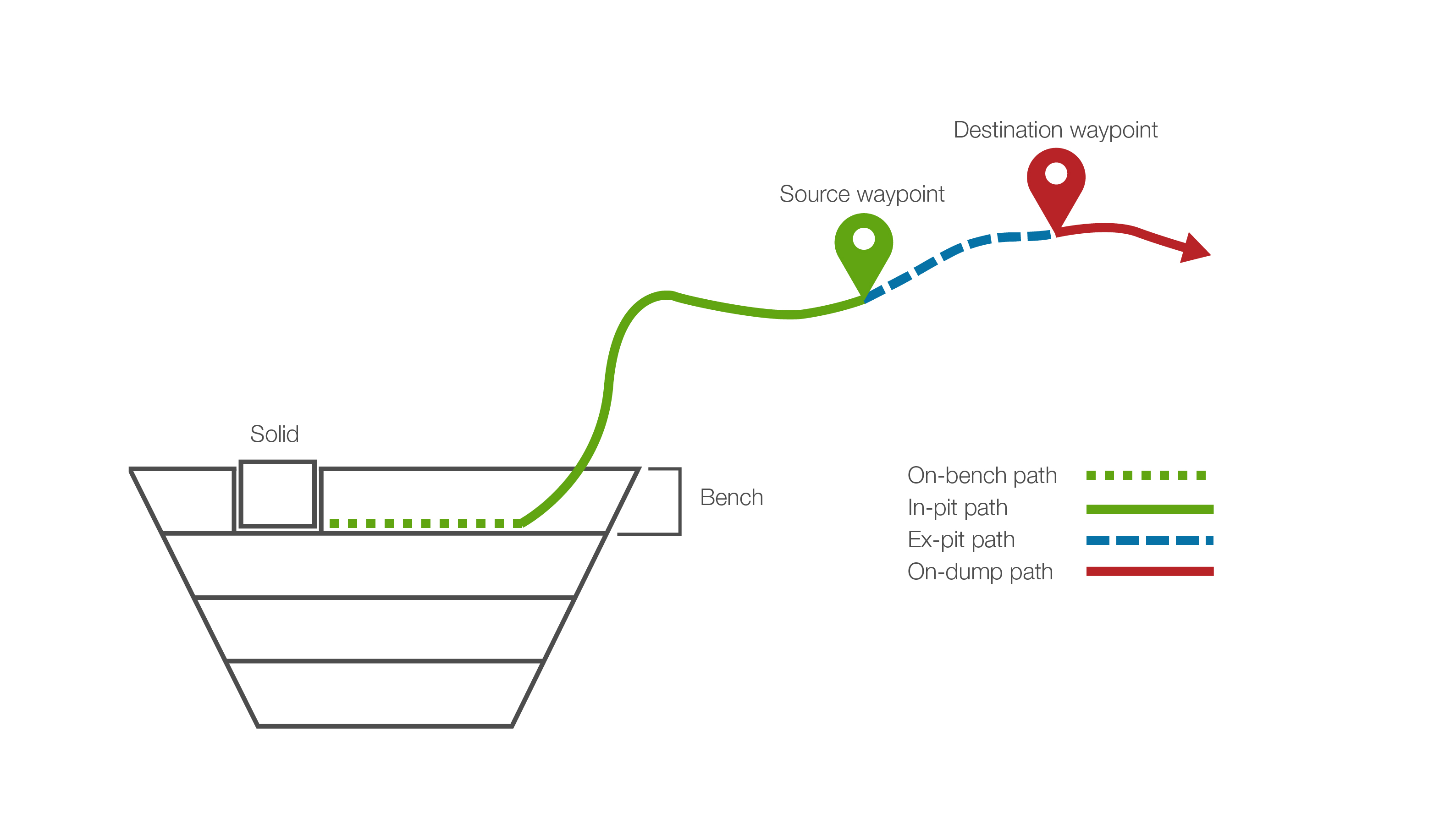
Every pathway must have the following components:
- A solid (or a block if talking about Origin Blocks setups)
- A source waypoint. An entry point onto the road network from the mining pit or a stockpile.
- A destination waypoint. An exit point from the road network to a destination such as a mill, stockpile or a waste dump.
- An on-bench path. A pathway from the solid through a ramp point in a bench to the road network.
- An in-pit path. A pathway between a solid and the first encountered source waypoint. Includes the on-bench path. Calculated from the perspective of a source waypoint (see below for explanation).
- An ex-pit path. In general, a pathway between a source waypoint and a destination waypoint.
Pathways that end in a waste dump will also contain an on-dump path, a pathway between a destination waypoint and the site of transfer.
Calculating the Best Route
When the software is asked to transfer a solid to a particular destination, it first calculates all the legal pathways to that destination, by first labelling each edge as in-pit or ex-pit from the perspective of each source waypoint. In the example below, we calculate the potential in-pit and ex-pit edges from Source A as a reference point.
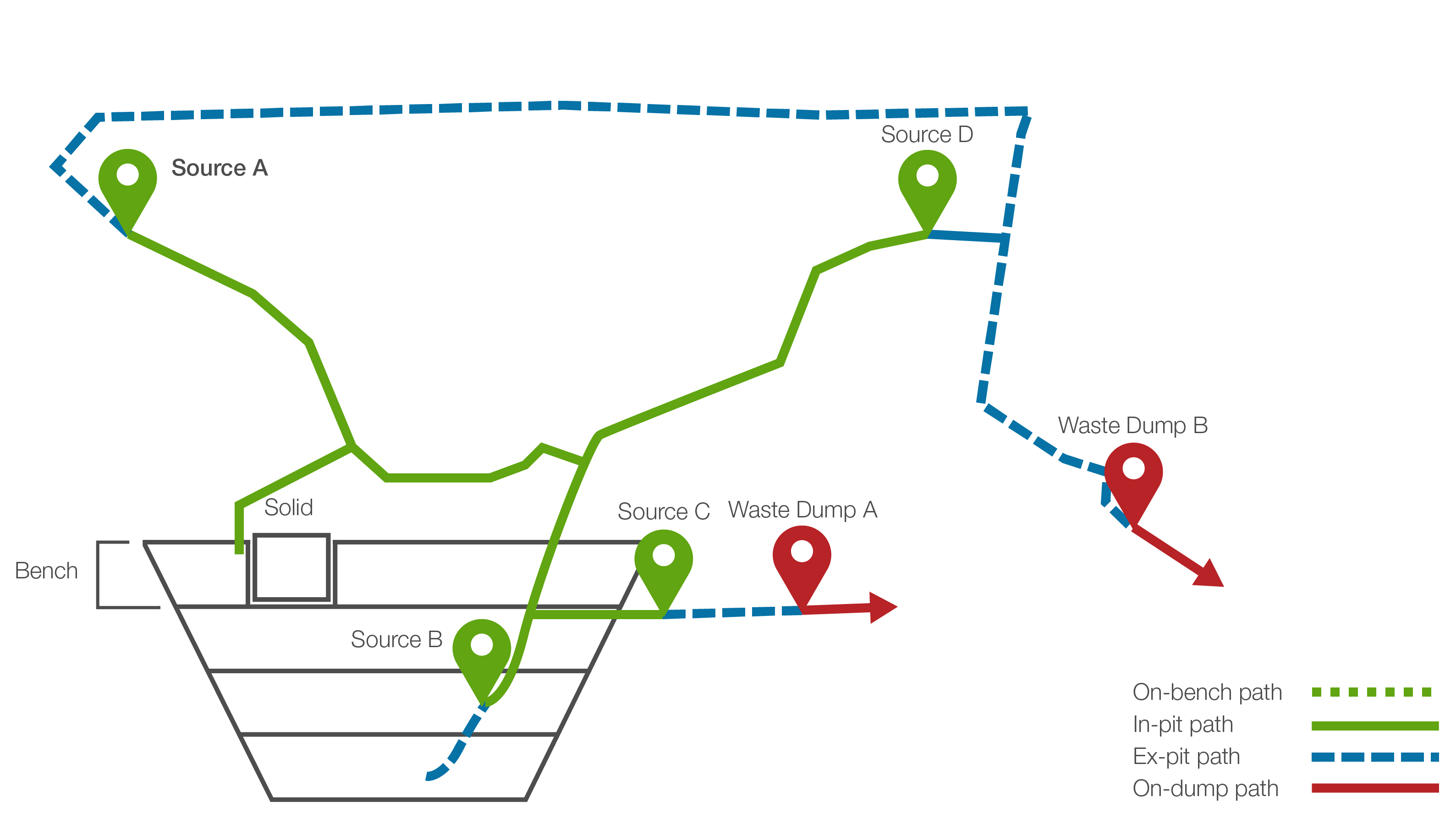
After labelling each edge, it finds the closest ramp point at the same height of the solid (called on-bench path) and then calculates the shortest in-pit path to Source A.
Once it calculates the shortest in-pit path, it can then find a corresponding ex-pit path and calculates the shortest path.
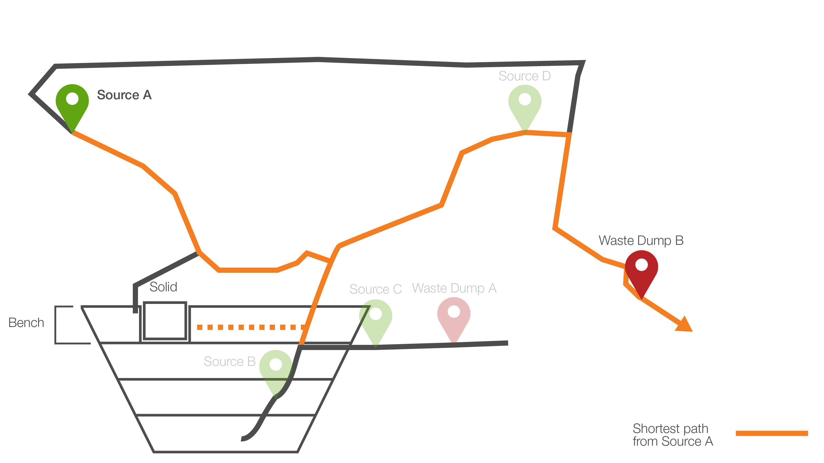
It then repeats this process for each source point and then chooses the best path. The best path is the one which has the lowest cost and the least amount of interpolation
Worked example #1: Internal sources and filters
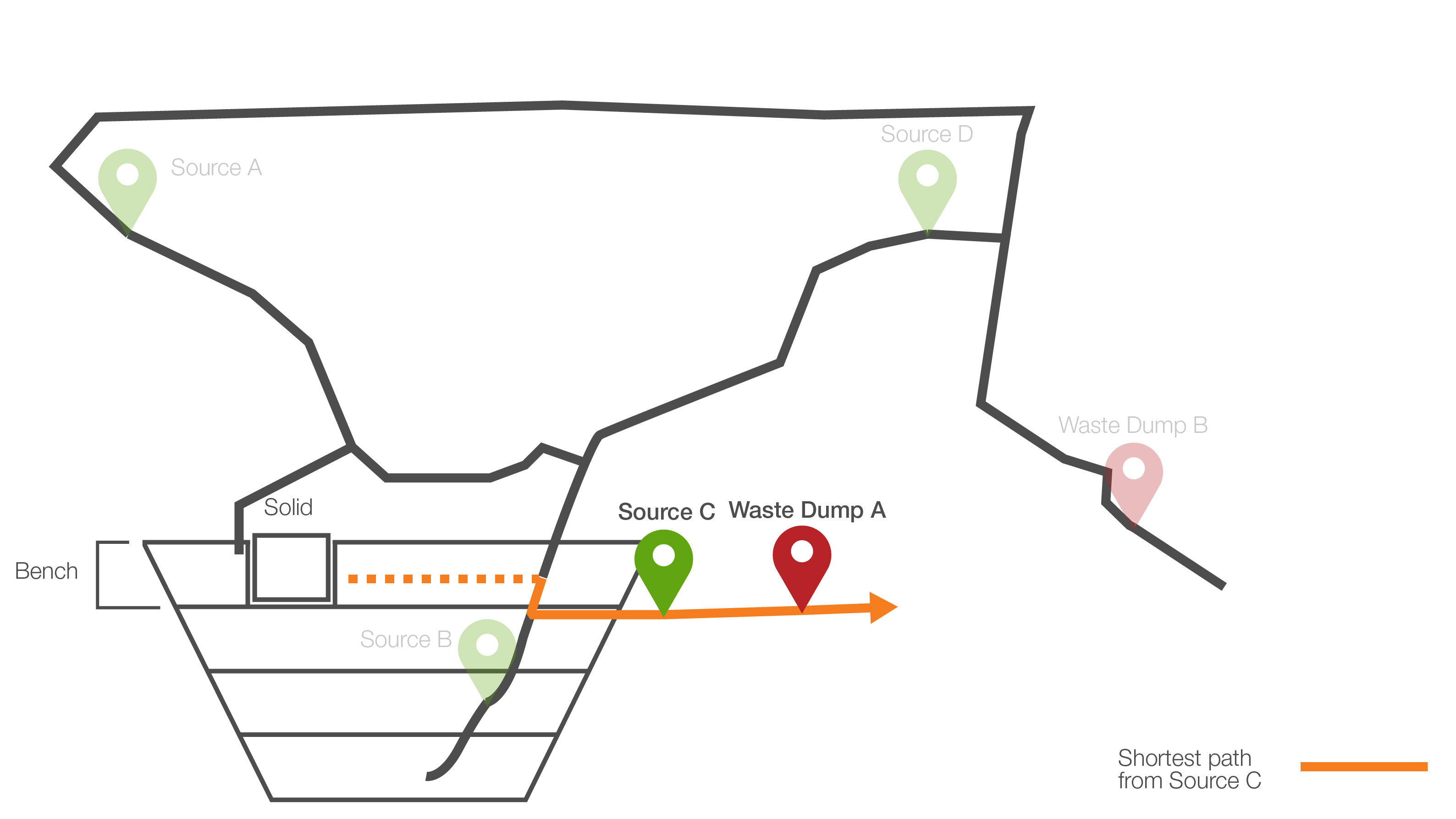
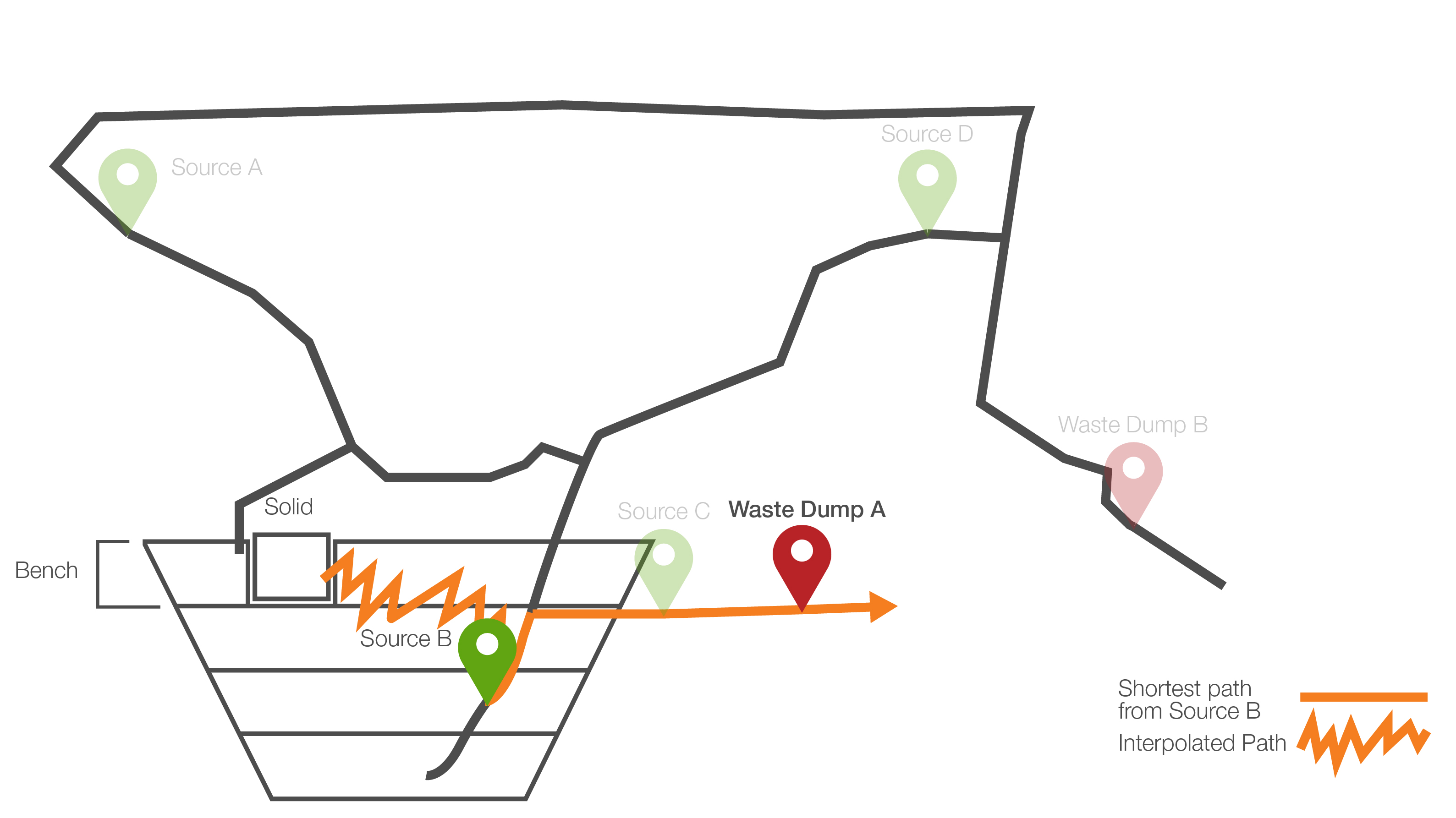
If this process is continued, the shortest legal paths between the source and mill destination point are between Source B and Waste Dump A, and Source C and Waste Dump A as illustrated below. However this path requires the digger to drill downwards, which is highly unlikely in the real world as it requires more fuel than driving horizontally.
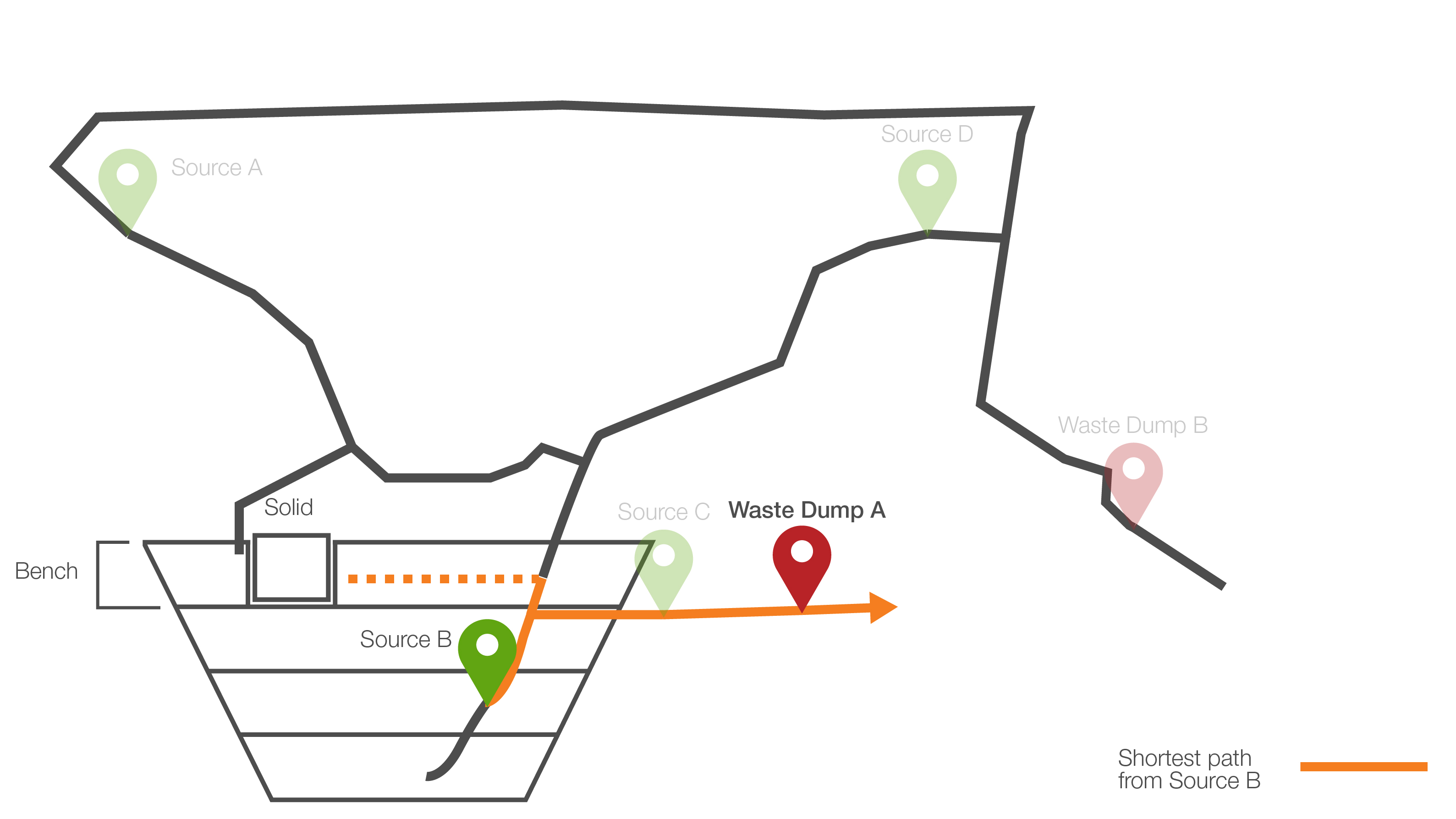
To stop such paths from being chosen, Evolution introduces the use of internal source points and filters.
By flagging a source waypoint as internal, such as source B in the example below, the software changes how it classifies potential paths as in-pit. Now, edges that are directly connected to the reference source waypoint and not directly connected to any other waypoint are considered in-pit.
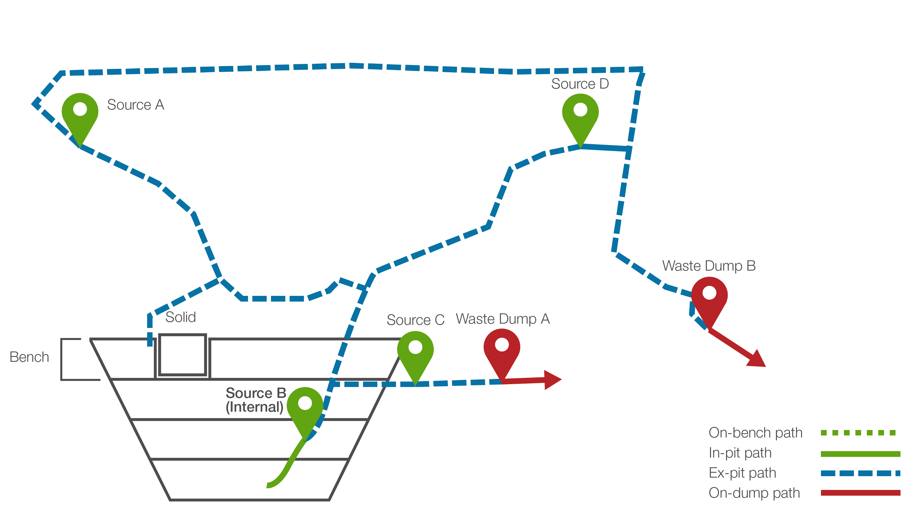
Previously, we defined a pathway as one with a source point, a destination point, an in-pit and an ex-pit path. Because there are no potential in-pit paths connected to Source B at the same height as the solid, the only way that a valid path can be created from Source B to the mill is if Evolution creates an interpolated pathway between the solid and source B, as shown below. While this pathway is shorter than those calculated previously, it is ranked lower in preference because it contains an interpolated path.
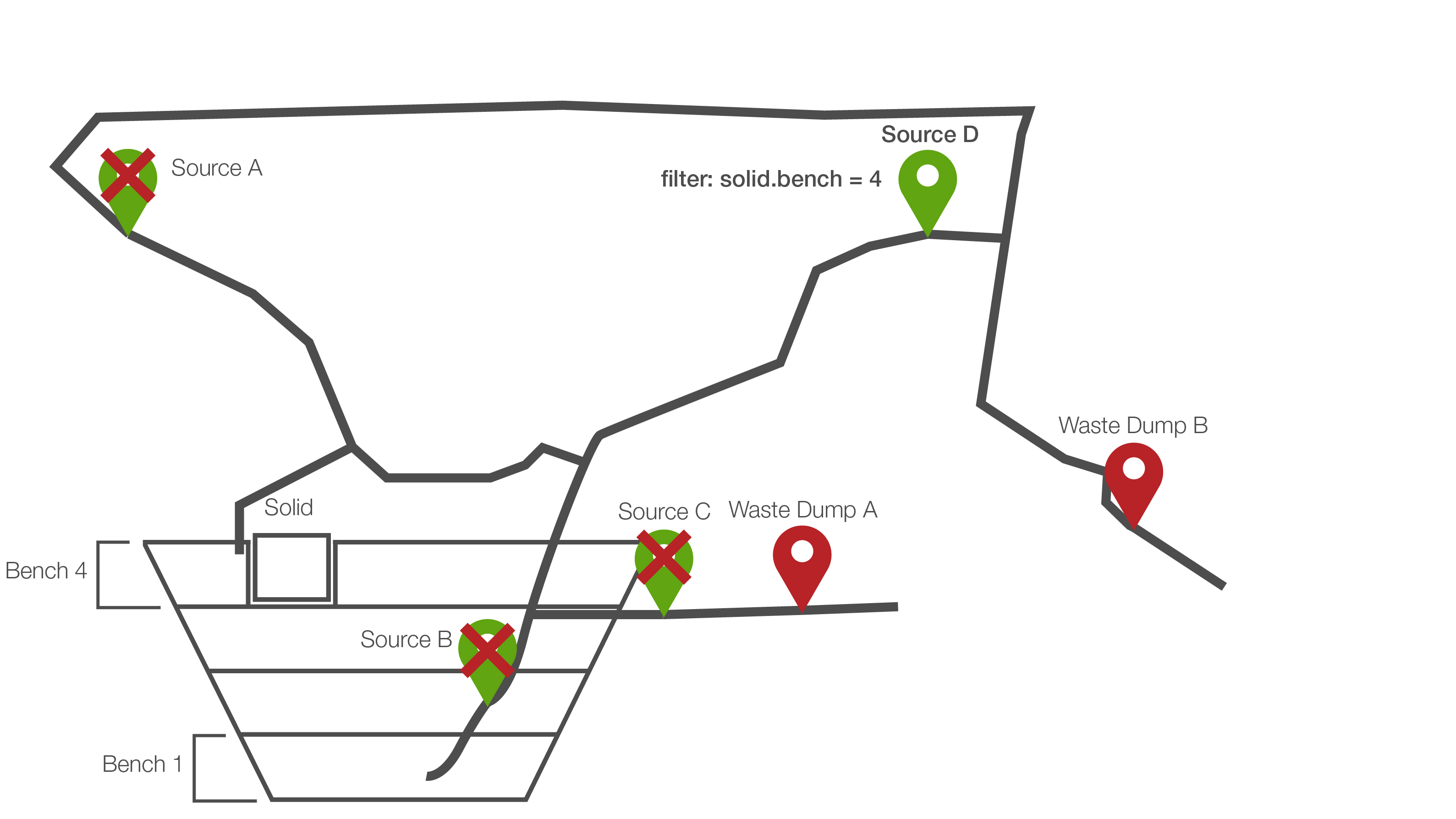
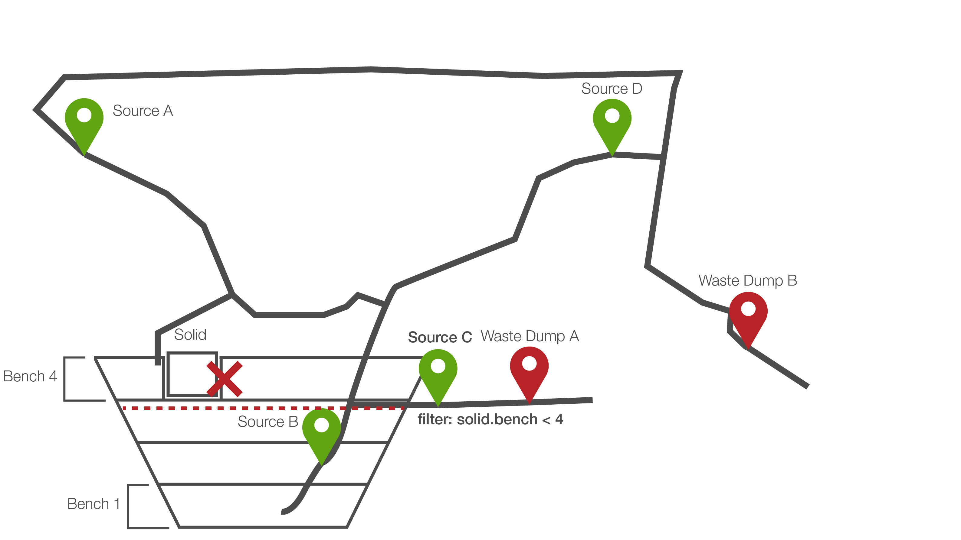
In our example above, the shortest path is still between Source C and Waste Dump A. Aside from flagging source waypoints as internal, filters can be applied to source points. In the diagram below, the filter solid.bench < 4 is used to prevent downward drilling behaviour. In other words, only material in solids with a bench less than 4 can use this source point to get to a destination. Therefore, calculations from Source C as a reference point are excluded for the particular solid in question.
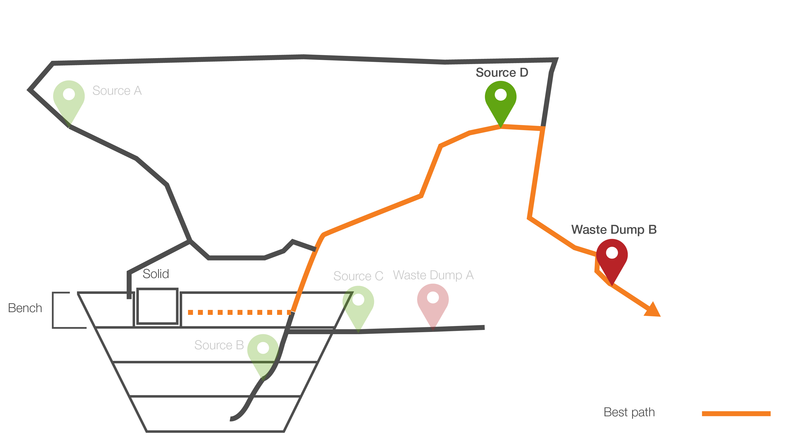
Therefore, the shortest path is now between Source D and Waste Dump B.
Worked example #2: Exclusive sources
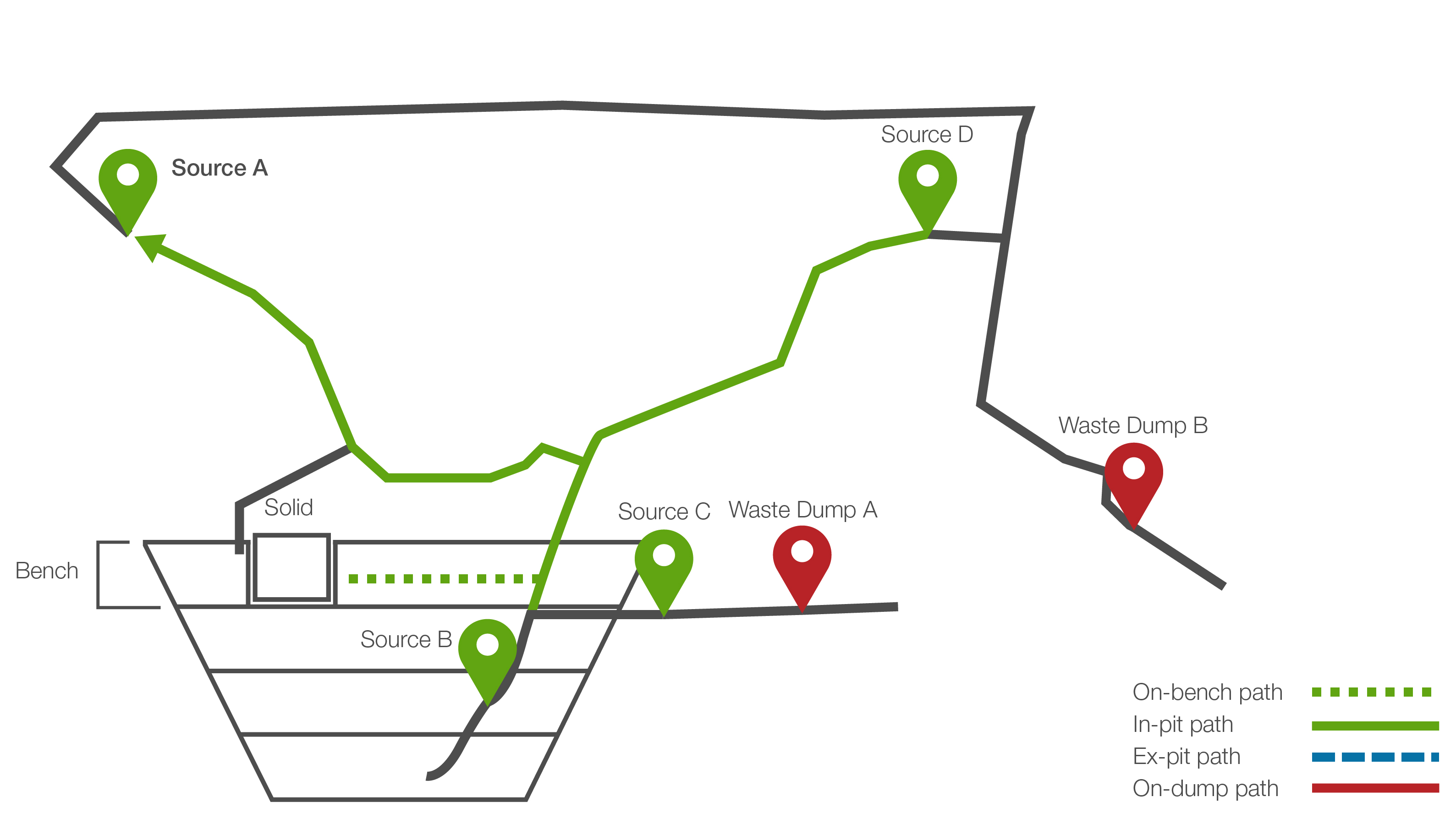
Evolution also allows you to flag source waypoints as exclusive. Making sources exclusive is another way of preventing unrealistic behaviour. For example, in the diagram below, the aim is to mine a solid from Bench 1. Again, we want to limit access to source waypoints B and C as this will involve downward drilling. We can make source D an exclusive source and apply a filter the following filter to it:
solid.bench = 4
This means that solids that belong to bench 1 must go through source waypoint D.