Material Flow
Source file: origin-block-setups-flowchart-flowchart.htm
The ![]() Material Flow subtab is used for adding process flow equipment to a setup and designing the flow of material.
Material Flow subtab is used for adding process flow equipment to a setup and designing the flow of material.
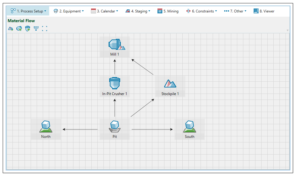
A number of components can be added as described in the table below. They are separated into two distinct types of components—virtual and imported. Virtual components are added from the toolbar and have no associated geometry. Imported components are stored in the project explorer and added to the setup via drag and drop.
| Icon | Label | Type | Description |
|
|
Mill | Virtual | A mill processes material sent from a pit. |
|
|
Pit (block) | Imported | Represents the in situ resource to be mined. The pit needs to be a block model to be added to an Origin Blocks setup. |
|
|
Waste dump (block) | Imported |
A waste dump stores waste material sent from a pit. It contains an associated geometry, which is useful when you want to pinpoint exactly where you are sending waste material to. For the imported waste dump to be successfully added to the setup, it needs to be a block model. Important: Imported waste dumps are only available in Equipment setups. In Material Movement setups, virtual waste dumps can be used instead. |
|
|
Virtual stockpile | Virtual | A reserve stockpile is a temporary storage site for low grade material. Later on in the schedule, material is sent from the stockpile to the mill to achieve end of period targets. |
|
|
In-pit crusher | Virtual |
An in-pit crusher is a semi-mobile crusher that reduces the size of the chunks of mined material by crushing them into smaller chunks directly in the pit, and facilitates transport to the processing nodes without further truck haulage. Note: Currently, each in-pit crusher can have only one outgoing link, and it must be connected to a mill. Note: You can add multiple in-pit crushers to your setup. |
|
|
Waste dump | Virtual |
A waste dump stores waste material sent from a pit. Important: Virtual waste dumps are only available in Material Movement setups. In Equipment setups, imported waste dumps can be used instead. |
Once components have been added, the flow of material can be defined by linking them together. To create a link between component A and B, complete the following steps:
-
Click on component A. A white circle with a black outline will appear in the middle of the component.
-
Click on the circle in the middle of component A an drag the arrow all the way to the black circle on component B and wait until the circle has a grey outline.
-
Release the mouse. The link will be created.
