Material Flow
Source file: epoch-setups-flowchart-flowchart.htm
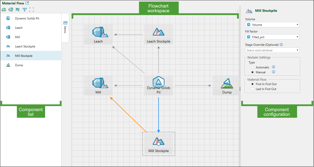
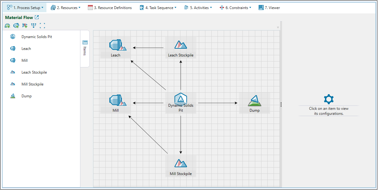
Use the ![]() Material Flow subtab to add, link, and configure each component in your setup. The Material Flow workspace consists of the following sections:
Material Flow subtab to add, link, and configure each component in your setup. The Material Flow workspace consists of the following sections:
-
List of components added to your setup.
-
Flowchart workspace (viewing window) where you can link all processing nodes to define the permissible material flow between all components in your setup.
-
Component configuration section where you can specify attributes, set parameters, and apply settings for each setup component.
Adding and viewing setup components
The table below outlines the processing nodes that you can add in Epoch as your setup components. Each item is categorised as either virtual or imported.
| Processing node | Type | Description |
|---|---|---|
|
Solid pit
Dynamic solids pit
|
Imported |
A pit represents a mining site. In Epoch setups, you can use solid pits, which are made up of irregularly shaped units described as solids, or dynamic solids pits, which are combinations of solid models and block models. See also: Solid Models, Dynamic Solids Pits, and Importing a Dynamic Solids Pit |
|
Mill
|
Virtual | A mill processes material sent from a pit. Generally, an overflow stockpile is situated adjacent to it for easy storage of low-grade material. |
|
Stockpile
|
Imported |
A stockpile is a temporary storage site for low-grade material. Later on in the schedule, material is sent from a stockpile to the mill to achieve end-of-period targets. See also: Importing a Solid Model, Simple Stockpiles |
|
Waste utility
|
Imported |
Waste utilities store waste material sent from a pit. Waste utilities contain geometrical information that helps you to pinpoint where material is sent. See also: Importing a Solid Model |
|
Waste dump
|
Virtual | Waste dumps store waste material sent from a pit. |
|
Flow Control
|
Virtual | A flow control node mimics the behaviour of a shaft in a mine. You can use it to limit the amount of material transferred between a pit and a destination. |
-
To add an imported processing node to your setup, import an external file with the model into your Evolution project. Next, drag the required model from the project explorer into the Material Flow workspace. See Importing a Solid Model for more information.
-
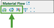
To add a virtual processing node to your setup, use the buttons provided in the Material Flow toolbar.
-
Click
 (Auto layout diagram) in the Material Flow toolbar to align components of your model to visualise precedence and dependencies between the nodes.
 -
Click
 (Size diagram to fit) in the Material Flow toolbar to place your diagram in the centre of the flowchart workspace.
 -
Zoom in and zoom out to navigate to the required components within the diagram.
-
Hold Ctrl to select multiple components in the diagram.
Note: When you select multiple components, only connections for the first selected component will be highlighted. See Linking setup components for more information.
The components that you have added to your setup will appear on the list of setup components on the left-hand side of the Material Flow screen. Click on the required component in the list to select it in the material flow diagram (and vice versa) and to open the component configuration panel (see Configuring setup components for more details).
Note: Moving components within the diagram will not change their order in the list.
-
Double-click the required component on the list to centre the material flow diagram on that component.
-
Select the component you no longer require by clicking on it in the material flow diagram or in the list, then press Delete.
-
Toggle the
 Items button to show or hide the list of components in your view.
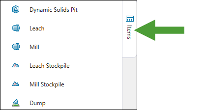
Linking setup components
After you have added all the required processing nodes, define the flow of material by linking them together. To create a link between component A and B, complete the following steps:
-
Click on component A.
A white circle with a black outline will appear in the middle of the component. -
Click on the circle in the middle of component A and drag the arrow to the black circle on component B, and wait until the circle has a grey outline.
-
Release the mouse.
The link will be created.
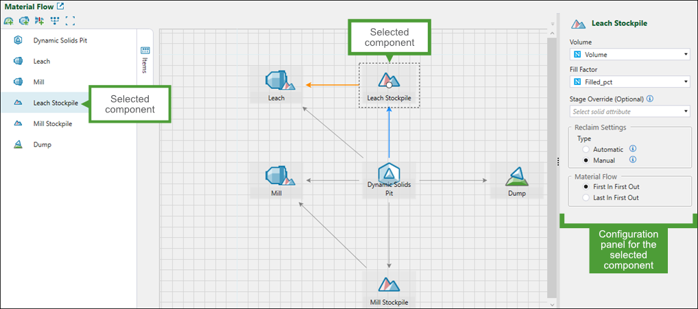
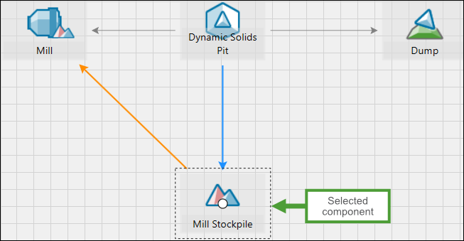
When you click on an individual setup component, the arrows representing material flow direction will be displayed as follows:
All incoming connections that indicate that the material can flow to that component will be highlighted in blue.
All outgoing connections that indicate that the material can flow from that component will be highlighted in orange.
Configuring setup components
When you click a component in the list or within the diagram, the component configuration panel will appear on the right-hand side of your screen. The type of information that you must provide depends on the component type.
Note: You must provide all mandatory information for a schedule to be generated. The non-mandatory fields are marked as (Optional).
Pit (solids)
For a standard solids pit, set the following fields using the attributes from the imported pit:
-
Tonnes: Provide the attribute that best represents the maximum tonnes.
-
Volume: Provide the attribute that best represents the maximum volume.
-
Available to Mine Factor: Provide the attribute that best represents the availability of a solid.
Note: The value of this attribute should range between 0 and 1 to describe the proportion of each solid that is available to be mined. The available material in a solid is calculated by the following equation:

Note: If you do not set Available to Mine Factor, all solids will be fully available to mine.
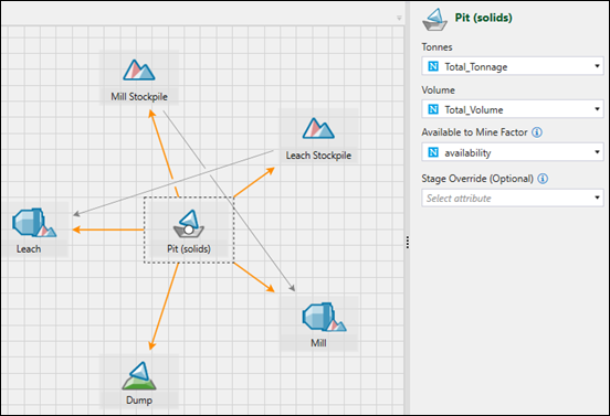
Note: Optionally, you can set Stage Override by selecting the required attribute from the drop-down. By default, Evolution uses the stage value provided in the model that you import. When you modify the stage value while configuring a pit in a setup, only the current setup will be affected. To modify the default stage value, right-click on your model in the project explorer, select ![]() Change Stage Attribute…, and specify the new attribute by selecting it from the drop-down.
Change Stage Attribute…, and specify the new attribute by selecting it from the drop-down.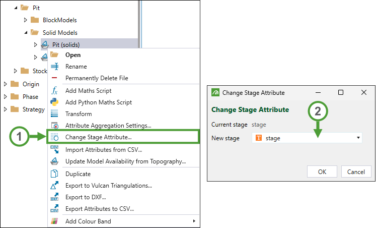
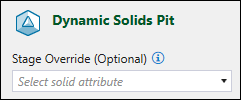
Pit (dynamic solids)
For a dynamic solids pit, you can (optionally) set Stage Override (see the note above for more information).
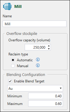
Mill
Configure the following fields for each mill in your setup:
-
Name. Provide a name for the mill. The default name is Mill <number>, where number represents the number of mills in the setup.
-
Overflow stockpile
-
Overflow capacity. Enter the overflow capacity of the stockpile adjacent to the mill. The greater the overflow capacity, the more likely it is for material to be sent to it.
Note: Stockpile capacities may be exceeded in scenarios with small capacities or high digger rates. You can minimise this by reducing the length of the reporting period. See Editing a setup for more information.
-
Reclaim type. Select either of the following radio buttons:
-
Automatic. Select to allow automatic reclaiming behaviour. If selected, Evolution will determine when to reclaim material from the stockpile, based on meeting blend targets and maximising equipment productivity. To meet these criteria, Evolution will assign equipment as needed for reclaim and will ignore any reclaim tasks defined in any task lists.
Note: This is the default behaviour for stockpiles.
Or
-
Manual. Select to only reclaim material from the stockpile based on reclaim tasks defined in task lists. If you do not define any reclaim tasks in the task lists, no material will be reclaimed from the stockpile. For more information on task lists and creating reclaim tasks, see Task Lists.
-
-
Blending Configuration
-
Enable Blend Target. Select to set a blend target for the mill. You can then specify the required target by selecting a pit attribute from the corresponding drop-down and defining the following:
-
Minimum. Set a minimum blending target for the final mined solid.
-
Maximum. Set a maximum blending target for the final mined solid.
-
-
-
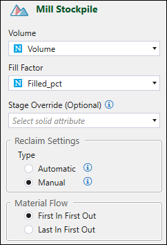
Stockpile
Configure the following fields for each stockpile in your setup:
-
Volume. Provide an attribute from the imported stockpile model that represents maximum volume for each unit of space (solid) within the model.
Note: Stockpile capacities may be exceeded in scenarios with small capacities or high digger rates. You can minimise this by reducing the length of the reporting period. See Editing a setup for more information.
-
Fill Factor. Provide an attribute from the imported stockpile model that represents the fill factor for each unit of space (solid) within the model.
-
Reclaim Settings
-
Type. Select either of the following radio buttons:
-
Automatic. Select to allow automatic reclaiming behaviour. If selected, Evolution will determine when to reclaim material from the stockpile, based on meeting blend targets and maximising equipment productivity. To meet these criteria, Evolution will assign equipment as needed for reclaim and will ignore any reclaim tasks defined in any task lists.
Note: This is the default behaviour for stockpiles.
Or
-
Manual. Select to only reclaim material from the stockpile based on reclaim tasks, defined in task lists. If you do not define any reclaim tasks in the task lists, no material will be reclaimed from the stockpile. For more information on task lists and creating reclaim tasks, see Task Lists.
-
-
Material Flow. Select either of the following options:
-
First In First Out. Select to ensure that the first solid sent to the stockpile is the first solid to be reclaimed. Evolution will select this option by default.
Or
-
Last In First Out. Select to ensure the last solid sent to the stockpile is the first solid to be reclaimed.
-
-
Note: Optionally, you can set Stage Override by selecting the required attribute from the drop-down. By default, Evolution uses the stage value provided in the model that you import. When you modify the stage value while configuring a stockpile in a setup, only the current setup will be affected. To modify the default stage value, right-click on your model in the project explorer, select ![]() Change Stage Attribute…, and specify the new attribute by selecting it from the drop-down.
Change Stage Attribute…, and specify the new attribute by selecting it from the drop-down.
See also: Simple Stockpiles
Waste utility (imported)
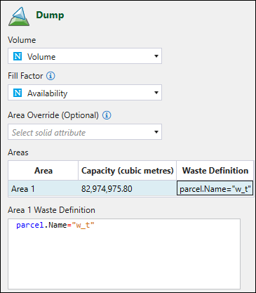
To configure a waste utility, set the following fields:
-
Volume. Select the attribute from the imported waste utility that best represents the maximum volume for each unit of space within the waste utility.
-
Fill Factor. Select the attribute from the imported waste utility that best represents the fill factor for each unit of space within the waste utility.
-
Waste Definition. Enter the script defining waste parcels.
Note: Optionally, you can set Area Override by selecting the required attribute from the drop-down. By default, Evolution uses the area value provided in the model that you import. When you modify the area value while configuring a waste utility in a setup, only the current setup will be affected. To modify the default area value, right-click on your model in the project explorer, select ![]() Change Area Attribute…, and specify the new attribute by selecting it from the drop-down.
Change Area Attribute…, and specify the new attribute by selecting it from the drop-down.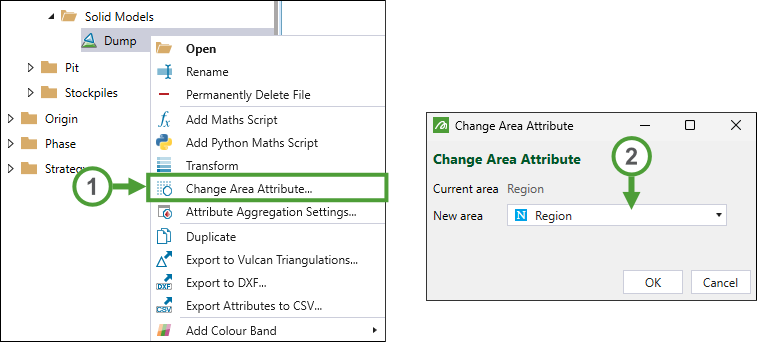
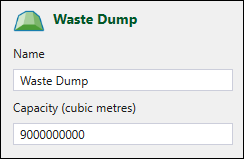
Waste dump (virtual)
A virtual waste dump only needs its name and capacity to be defined.
Note: For virtual waste dumps, you can set the per-period waste definition in the ![]() Resource Definitions tab. See Resource Definitions for more information.
Resource Definitions tab. See Resource Definitions for more information.
Flow Control
Define the following flow control parameters:
-
Name. The default name is Flow Control <number>, where number represents the number of flow control nodes in the setup.
-
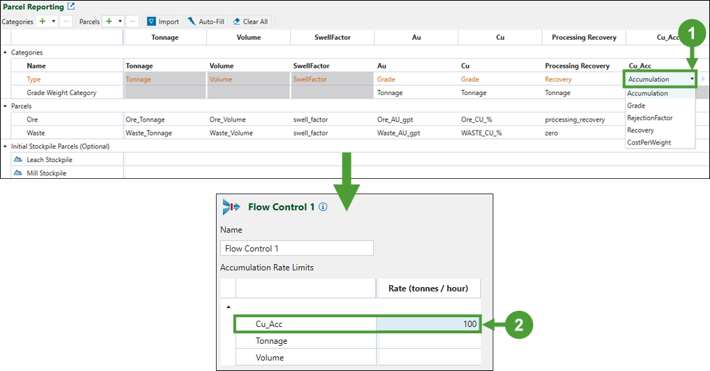
Accumulation Rate Limits. Limit the quantity of material passing through the flow control node by setting the accumulation rate (tonnes/hour). The node will ensure that no accumulation exceeds the specified rate over all steps through time.
You can set a limit for the following accumulation items:-
Tonnage
-
Volume
-
Custom accumulation item
Note: If you leave an accumulation item blank, this item will not be limited.
-
To set a custom accumulation item, you must define it first in the ![]() Parcel Reporting subtab. To do so, add a custom category and specify its type as Accumulation. Next, go to the
Parcel Reporting subtab. To do so, add a custom category and specify its type as Accumulation. Next, go to the ![]() Material Flow subtab and specify the accumulation rate limit for the newly added parcel item.
Material Flow subtab and specify the accumulation rate limit for the newly added parcel item.
For more information on adding reporting items to your setup, see Parcel Reporting.
Tip: Once you validate your setup, you can check whether the limit that you had set is honoured by creating a pivot report.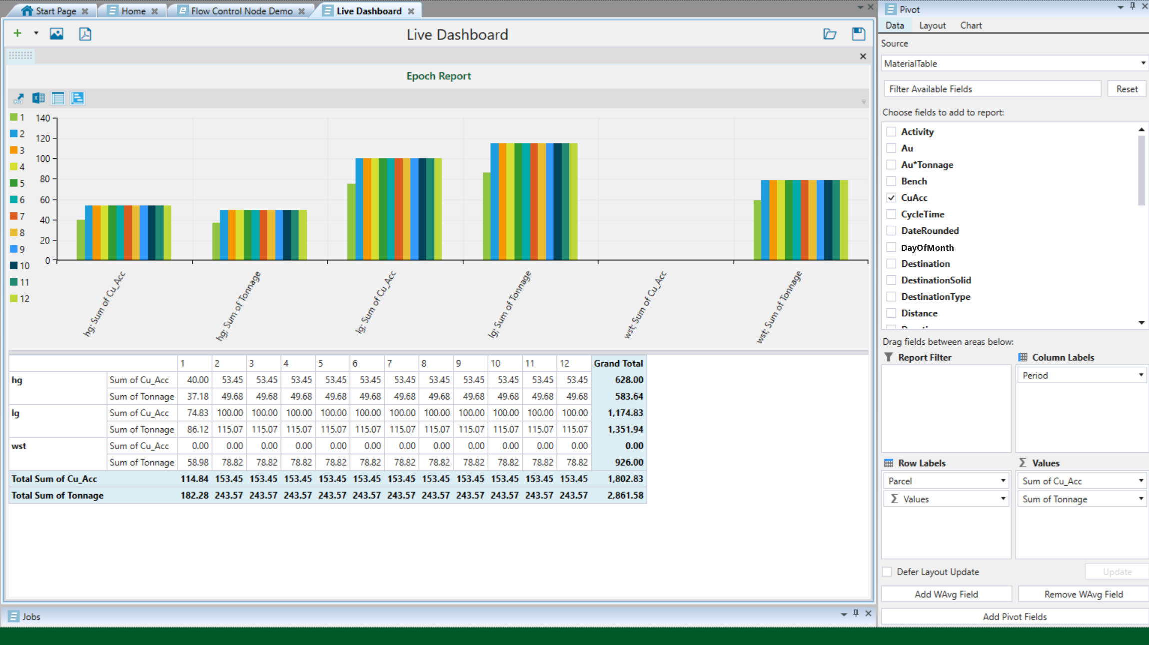
See Pivot Reporting for more information.
When checking whether the flow control rate has been enforced, you must consider the following competing rates:
The mill productivity set in the
 Resource Definitions panel (see Resource Definitions for more information).
The productivity rate set in the
 Activities >
  Resource Productivity tab (see Resource Productivity for more information).
The flow control rate must be lower than both the mill productivity and the productivity rate to be enforced by Evolution.
