Surface
The following table describes the tools in the Surface section of the Create tab.
| Tool | Description |
| Topographic | Used to create triangulations (surfaces) of a group of scans. |
| Extrusion | Used to create extrusions from objects such as polygons, lines or circles |
| Planar | Creates surface triangulations in a defined plane. |
| Loop | Creates a triangulation from a selection of loops or triangulations. |
| Complex 3D | Creates 3D surfaces from point clouds. |
| Hull | Creates a solid convex hull from the selected objects. |
| Fitted Plane | Fits a plane to a selection of points. |
| Solid Extent | Creates a solid extent in a defined plane. |
| Grid | Creates a surface from any data containing points. |
| Calculator | Creates new grids using arithmetic operations on existing grids. |
| Convert | Convert a grid to a triangulation surface. |
Topographic
This function works in the XY plane, that is, it triangulates straight down. This means that if there are areas of undercut walls, these will not be modelled accurately (in this case, use Spherical triangulation).
This option is used once scans have been registered (using Register scans by name, Matching point pairs or Translate / Rotate) and filtered (using Polygon, Isolated points, Topography and Intensity).
To create a topographic triangulation:
-
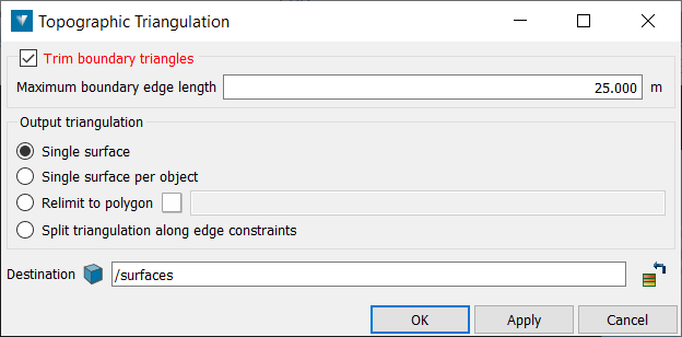
Go to Create > Surface > Topographic. This will open a new panel.
-
Check Trim boundary triangles to eliminate long, incorrectly generated boundary triangles. A maximum length is specified, which prevents triangles greater than this being created. Note: This option is only applicable to boundary triangles; large voids in the centre of the data will still be modelled.
-
For the output triangulation, select one of the following options:
-
Single surface creates a single surface from the selected objects/scans.
-
Single surface per object creates a single surface for each selected object/scan.
-
Relimit to polygon constrains the model to a polygon, for example a pit boundary. You will need to drag and drop a polygon into the field.
-
Split triangulation along edge constraints splits the triangulation into separate objects based on any lines or polygons highlighted in the Explorer window when the triangulation is created.
-
-
Ensure the scan data is highlighted in the Explorer window and click OK or Apply.
The triangulation is saved in the surfaces container by default.
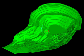
The example below shows a topographic triangulation of a pit with the Relimited to a polygon option selected.
Extrusion
To create an extrusion:
-
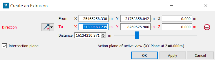
Go to Create > Surface > Extrusion. This will open a new panel.
-
Highlight the object from which to create the extrusion.
-
Specify the Direction and Distance of the extrusion.
-
If the extrusion must be terminated by an intersecting plane, rather than by a defined distance, select Intersect with a plane and specify the Intersection plane.
The extrusion will be saved in the cad container.
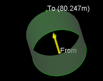
The example below shows an extrusion created from a circle.
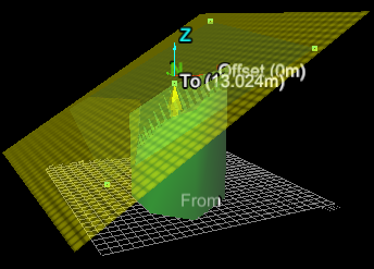
The example below shows an extrusion created from a polygon and extruded up to a plane.
Planar
Planar triangulation is used to create triangulation surfaces from any data containing more than three points. This function works in any defined plane, so that vertical or subvertical data, such as fault planes, can be modelled.
To use this tool:
-
Go to Create > Surface > Planar. This will open a new panel.
-
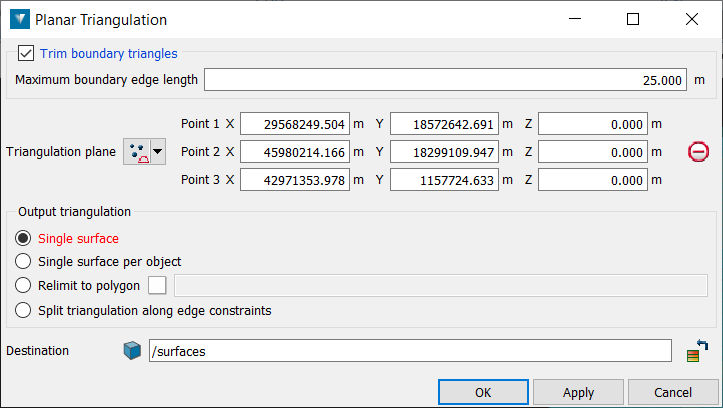
Check Trim boundary triangles to eliminate long, incorrectly generated boundary triangles. When ticked on, specifying a maximum boundary edge length prevents triangles greater than this being created. Note: This option is only applicable to boundary triangles; large voids in the centre of the data will still be modelled assuming they're enclosed by smaller triangles.
-
Define the orientation for the triangulation plane so that it is aligned subparallel to the data. The input geometry may be changed by selecting the Triangulation plane from the drop-down list.
-
Three points — Select three point coordinates to define a plane.
-
Point and normal — Select a point for the plane centre, then select a second point for the plane to be normal to.
-
Point and orientation — Select a point coordinate to define the location of the plane. The plane will be relative to the View orientation.
-
Facet and offset — Select a facet on a triangulation by clicking in the View window, then enter an Offset distance. The direction will be normal to the facet.
-
Point, strike and dip — Select a point coordinate, then define a dip (-90 to 90 degrees) and strike (0-360 degrees).
-
Axis aligned — Select a point coordinate, then select an axis (x, y, z).
-
Action Plane — Automatically chooses the action plane of active view.
-
-
Specify an option under Output triangulation to define what objects are created:
-
Single surface creates a single triangulation from the selection.
-
Single surface per object creates separate triangulations for each selected object. Surfaces generated by this method are stored in the surfaces container and named according to the parent object.
-
Relimit to polygon constrains the model to a polygon, for example a tenement boundary.
-
Split triangulation along edge constraints splits the triangulation into separate objects based on any lines or polygons selected in the Explorer window when the triangulation is created.
-
-
Ensure the data to be triangulated is selected in the Explorer window or View window and click OK or Apply.
The triangulation is saved in the surfaces container by default.
Loop
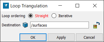
Loop triangulation is used to create a triangulation solid from a selection of loops or triangulations.
-
Select two or more polygons or triangulations.
-
Go to Create > Surface > Loop. This will open a new panel.
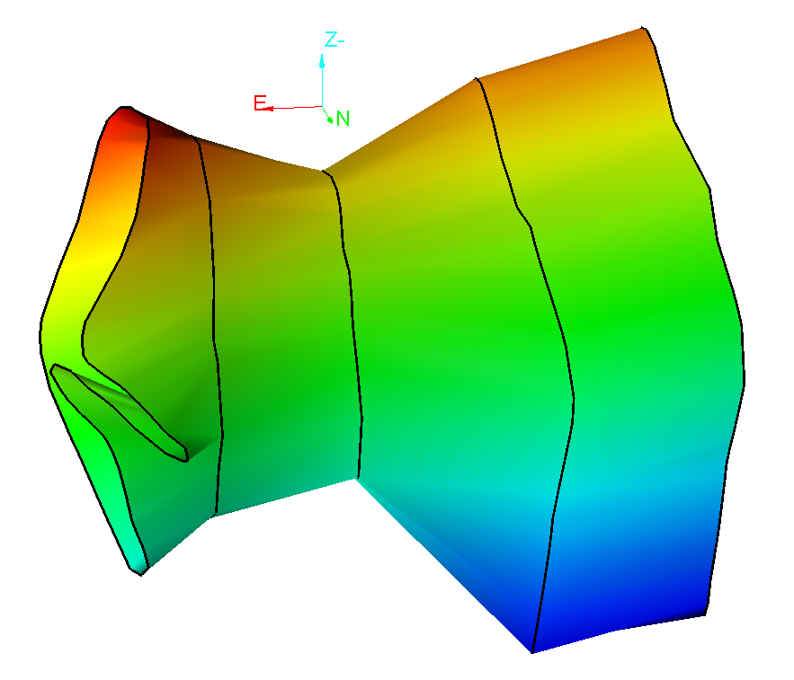
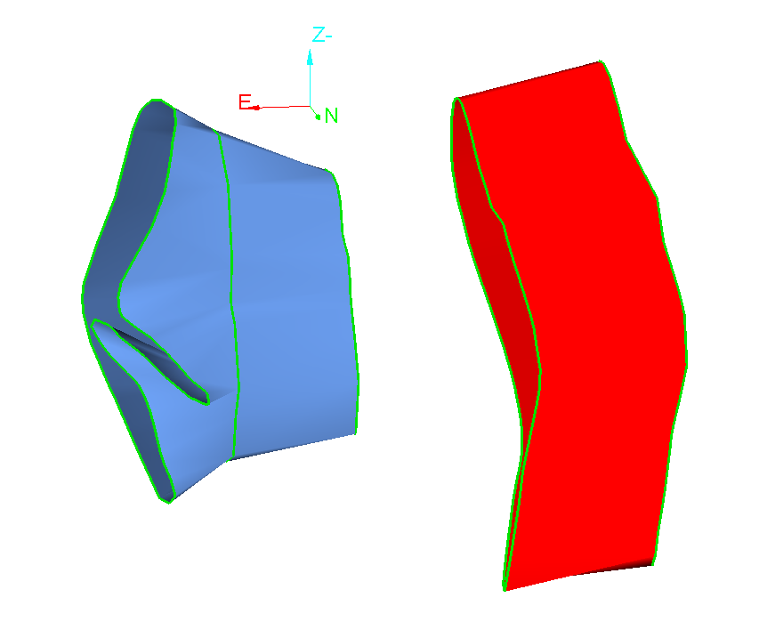
If there are two loop triangulations, selecting them and applying loop triangulation will create a new loop triangulation to fill any gap between the two loops, as shown below.
End plates can be constructed using theFill holes function.
Complex 3D
The Complex 3D surface provides a simple solution for creating surfaces from point clouds where the existing methods may not be able to adequately model all nuances of the actual ground. The method only requires an input guide to the smallest feature size, then will attempt to piece together the surface based on points within proximity of each other, regardless of orientation. This approach is quite successful at detecting and incorporating even small indents, overhangs and caves/holes that other surfacing methods would miss.
To use this tool:
-
Go to Create > Surface > Complex 3D. This will open a new panel.
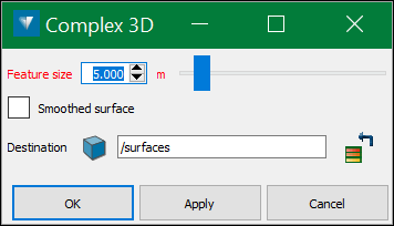
Set the desired Feature size and click on OK.
Note: Holes may occur in the model if the feature size guide is too small and the procedure cannot find a neighbouring point close enough to connect to. Larger feature sizes will result in less holes in the triangulation but will also result in less detail representing the true shape of the stope/ground.
-
Two surfaces will be created in the Surfaces container. A Triangulation on projected points and Triangulation on original points. Choose one triangulation to continue the process with and view it in a new view window.
Note: The facets of the triangulation on original points are created from the scan points used to create the surface and is more true to the real world surface but can be very spiky and jagged. The facets of the triangulation on projected points are a best fit of the scan points and will be smoother and have less spikes.
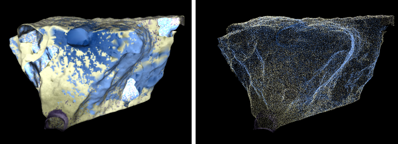
An example of a Complex 3D surface.
Hull
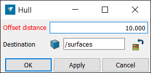
The Hull function creates a solid convex hull from selected objects. It is used to provide a boundary around the data to limit the model.
To use this function:
-
Select some sample points or drillholes.
-
Go to Create > Surface > Hull. This will open a new panel.
-
Set the Offset distance which is, the distance between the last sample point and the boundary solid.
-
Set the Destination of the resulting solid convex hull.
Fitted Plane
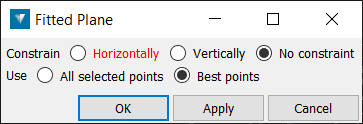
Fitted planes (Ctrl+K) are used to fit a best fit plane to a selection of points. This may be useful if creating a fault plane for visualisation.
-
Using the point selection tool
 , select the group of points to have a plane fitted.
 -
Select Create > Surface > Fitted plane. This will open a new panel.
-
Select whether the plane should be constrained Horizontally or Vertically. No constraint will use the best fit for the plane.
-
Select All selected points to use all the points in the selection to fit the plane. Select Best points to discard the outlying points.
The plane is saved as a triangulation in the cad container and is coloured the average colour of the selected points.
Solid Extent
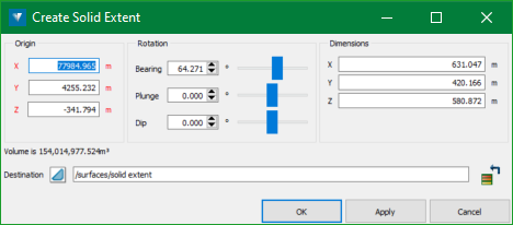
The Solid Extent tool allows to create a solid extent triangulation, with the ability to preview in the current view. It employs a translation and rotation manipulator to easily modify the position and rotation of the extent. Any selection will change the extent to be the bounding extent of the selection.
-
Load the objects on the screen.
-
On the ribbon, navigate to Create > Surface > Solid Extent or Modelling > Domain Modelling > Model Extents. The following panel is displayed.
-
Enter the origin, rotation, and dimensions manually.
-
Optionally, a translation and rotation manipulator also appears on the lower left corner of the screen.
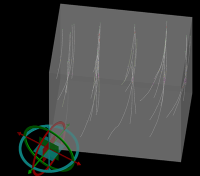
-
Adjust the position and rotation of the extent using this manipulator. The values will be automatically reflected on the Create Solid Extent panel.
-
Once you find a perfect position, press OK. The solid extent is created as a closed surface.
Grid
Grids (Alt+G) are two-dimensional surfaces which can be created from any data containing points. Grid meshes are useful, especially when irregularly spaced and/or sparse data sets occur. They have a distinct advantage that they can be calculated very quickly, and store multiple attributes allowing data trends and residuals to be coloured and viewed easily.
-
Select the required objects.
-
Select Create > Surface > Grid.
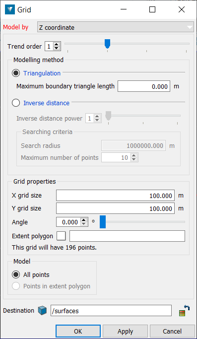
A transient grid is displayed in the View window over the object, showing the grid size and angle.
-
Select the attribute to base the grid on from the Model by drop-down list. Note: Only attributes present in the highlighted object are available in the list.
-
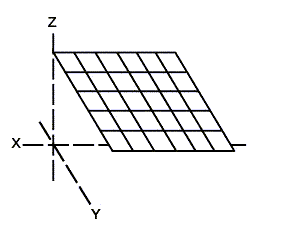
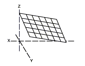
Enter a Trend order to model by.
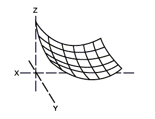
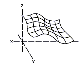
|
Trend order: 0 |
Trend order: 1 |
Trend order: 2 |
Trend order: 3 |
|---|---|---|---|
|
|
|
|
|
|
Plane at a mean Z value. |
1st order - a planar fit (an inclined horizon) |
2nd order - a simple paraboloid shape of a dome or trough (anticlinal or synclinal) |
3rd order - a combination of dome and trough |
-
Select the required Modelling method. Triangulation is used for modelling physical properties, Inverse distance is used for modelling chemical properties.
-
If the Triangulation modelling method is selected, enter the Maximum boundary triangle length. Any boundary triangles larger than the entered maximum will be removed. Note: A length of zero means that no triangles will be removed.
Break lines can be used to model faults by including the lines in the selected objects, forcing the model to adhere to edges. The Z value of the break lines is included in the modelling.
-
If the Inverse distance modelling method is selected:
-
Inverse distance power is used to vary the gradient of the results. (Higher values produce a steeper decline around data points.)
-
Search radius is the distance from each grid intersection within which data points will affect the resultant model.
-
Maximum number of points defines the number of points within the search radius that will be used to generate the results.
-
Select All points to model the entire object, or Points in extent polygon to model only within the selected Extent polygon.
-
Enter the required X and Y grid size.
-
Select the Angle at which to generate the grid. The transient grid display moves as the angle is adjusted.
-
Select the location to save the grid.
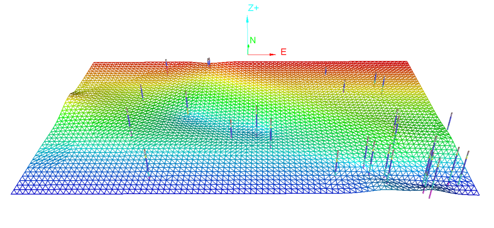
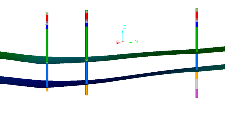
Below is an example of a grid modelling the top of a sandstone formation which was selected from a set of drillholes
Calculator
Allows the creation of new grids ![]() from pre-existing grid and scalar values. The grids must be exactly aligned.
from pre-existing grid and scalar values. The grids must be exactly aligned.
Possible operations which can be performed to create the new grid model are:
+ : Add the modelled attribute of a grid to another grid or scalar.
- : Subtract the modelled attribute of a grid from another grid or scalar.
* : Multiply the modelled attribute of a grid by another grid or scalar.
/ : Divide the modelled attribute of a grid by another grid or scalar.
Max(): Select the maximum value from the variables contained in brackets (e.g. Max (A,0) selects the higher value between variable A and 0).
Min(): Select the minimum value from the variables contained in brackets (e.g. Min (A,0) selects the lower value between variable A and 0).
Log(): Calculates the log of the variable contained in brackets.
Abs(): Uses the absolute (positive) values for the variables contained in brackets and converts negative values to positive (e.g. a value of -10 becomes 10).
Note: The calculator is not case sensitive.
-
Select Create > Surface > Calculator. This will open a new panel.
-
Select the grids to be used in the modelling by dragging and dropping into fields labelled A, B, etc.
-
Write an expression to define the operations to be performed on the grids.
-
Click OK or Apply to create the new grid.
Example
Using the calculator, new grid surfaces can be created by using existing grids as the input. A grid surface representing the top of a horizon can be calculated, by using a grid for the bottom of a horizon and a grid modelling the thickness. Doing so will ensure the top and bottom surfaces do not intersect.
-
Select the required drillholes
 .
. -
Go to Stratigraphic > Correlation > Select Intervals by > Stratigraphy.
-
Select the bottom of the interval using the drop down menu. Select the tickbox beside the horizon to be modelled.
-
Click OK to complete the selection.
-
Create a grid of the interval bottom.
-
Create a grid of the interval thickness by using the Stratigraphic > Correlation > Select Intervals by > Stratigraphyand selecting interval from the drop-down menu.
-
Create a grid of the interval selection to model the interval thickness.
-
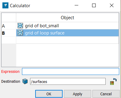
Go to Create > Surface > Calculator.
-
Drag and drop the grids into fields A and B
-
Enter the expression A + Max(B,0) where A is the interval bottom and B is the interval thickness.
-
Specify a name for the grid and click OK to create the grid. Grids are created in the surface container by default.
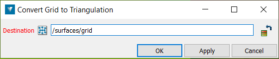
Convert
Converts a grid to a triangulation. A triangulation is a 3D surface composed of triangular elements.
-
Select the grid to be converted.
-
Go to Create > Surface > Convert. This will open a new panel.
-
Enter the destination for the converted triangulated surface.
-
Click OK or Apply to continue. Cancel will exit without any actions.