Text
The following table describes the tools in the Text section of the Create tab.
| Tool | Description |
| Create 3D | Labels data in a view with scalable text that may be fitted to a plane. |
| Edit 3D | Edits the properties of 3D text labels. |
| Create 2D | Labels data in a view. |
| Edit 2D | Edits the properties of 2D text labels. |
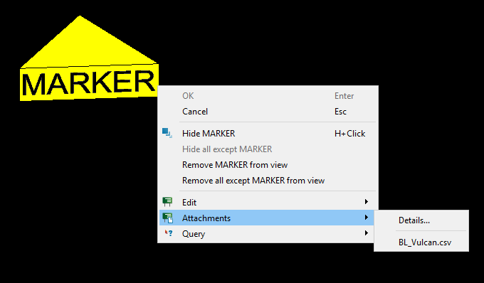
| Create Marker | Creates a locality marker which can store file attachments. |
| Edit Marker Properties | Edits the location and appearance of selected markers. |
| Edit Marker Attachments | Edits the attachments of a marker. |
Create 3D
3D text can be used to label data in a View window. 3D text is created by defining a plane in which the text will lie. Unlike 2D text, 3D text is fixed to this plane and its relative size does not change depend on zoom level. Contour labels are an example of 3D text.
-
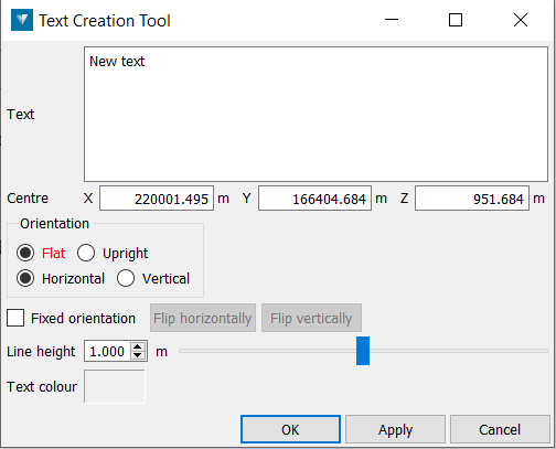
Go to Create > Text > Create 3D Text. This will open a new panel.
-
Type in the required text.
-
Click in a location field and enter the information or click in the View window to fill all the fields.
-
Centre — The position of the centre point of the text.
-
Direction — The left and right orientation of the text.
-
Up direction — The plane in which the text is positioned. This plane is specified by the value specified in Centre, Direction and Up direction. Note that the Up direction is always forced to be perpendicular to the Direction of the text.
-
-
Enter the required Line height for the text, or use the slider bar to specify the value.
The created 3D text is stored in the cad container.
Edit 3D
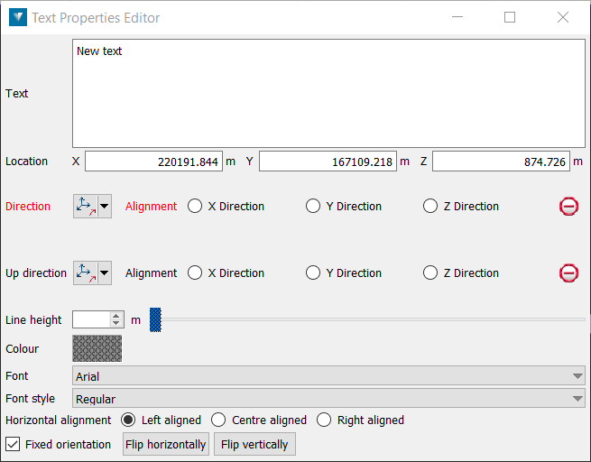
The Text property editor is used to adjust colour, font, size and alignment of text created.
-
Select the text to be edited in the Explorer window.
-
Select Create > Text > Edit 3D text properties. Note: This dialog may also be accessed by right-clicking on text in a View window and selecting Edit > Properties.
-
Change the Location, Direction, Up direction, Line height, Colour, Font, Font Style or Horizontal alignment if required.
Create 2D
2D text (Alt+T) can be used to label data in a View window. Unlike 3D text, 2D text always faces the view and its relative size changes depending on zoom level. This means that 2D text is always visible and readable regardless of view orientation and zoom level. Drillhole collar labels are an example of 2D text.
-
Select Create > Text > Create 2D Text.

-
On the status bar, enter the text location, or click in the View window. You will then be prompted for the text.

-
Enter the required text and press ENTER.
The 2D text is displayed in the View window and saved in the cad container.
Edit 2D
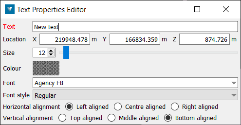
The Text property editor (Ctrl+Shift+T) is used to adjust colour, font, size and alignment of text created.
-
Select the text to be edited in the Explorer window.
-
Select Create > Text > Edit 2D text properties. Note: This dialog may also be accessed by right-clicking on text in a View window and selecting Edit > Properties.
-
Enter new Text if required.
-
Change the centre point by clicking in the Location fields to activate them, then clicking a new point in the View, or manually entering new coordinates. Right-clicking in these fields gives the option to use the coordinates of the selection centre.
-
Change the text colour, font, and font style if required.
Changing the Line height adjusts the distance between lines of text.
Changing the Horizontal alignment or Vertical alignment adjusts where the text sits relative to the Centre coordinate.
Create Marker
The marker object provides a way of creating markers at strategic locations in a View window and adding attachments to the marker which are relevant to these locations. The marker consists of a name (text), which is visible when zoomed out from the location. As you zoom in, the name fades away and a marker shape becomes visible.
The attachments allow notes, reports, photographs, diagrams and video files to be easily accessed from a marker which creates visual cue within a View window.
-
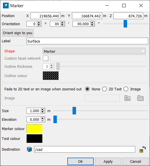
Go to Create > Text > Create Marker. This will open a new panel.
-
Change the centre point by clicking in the Position fields to activate them, then clicking a new point in the View, or manually entering new coordinates. Right-clicking in these fields gives the option to use the coordinates of the selection centre.
-
Select the Orientation of the marker, or nominate that the sign's face remains perpendicular to the viewer by using Orient sign to you.
-
Change the text to be displayed at the marker location in the Label field if required.
-
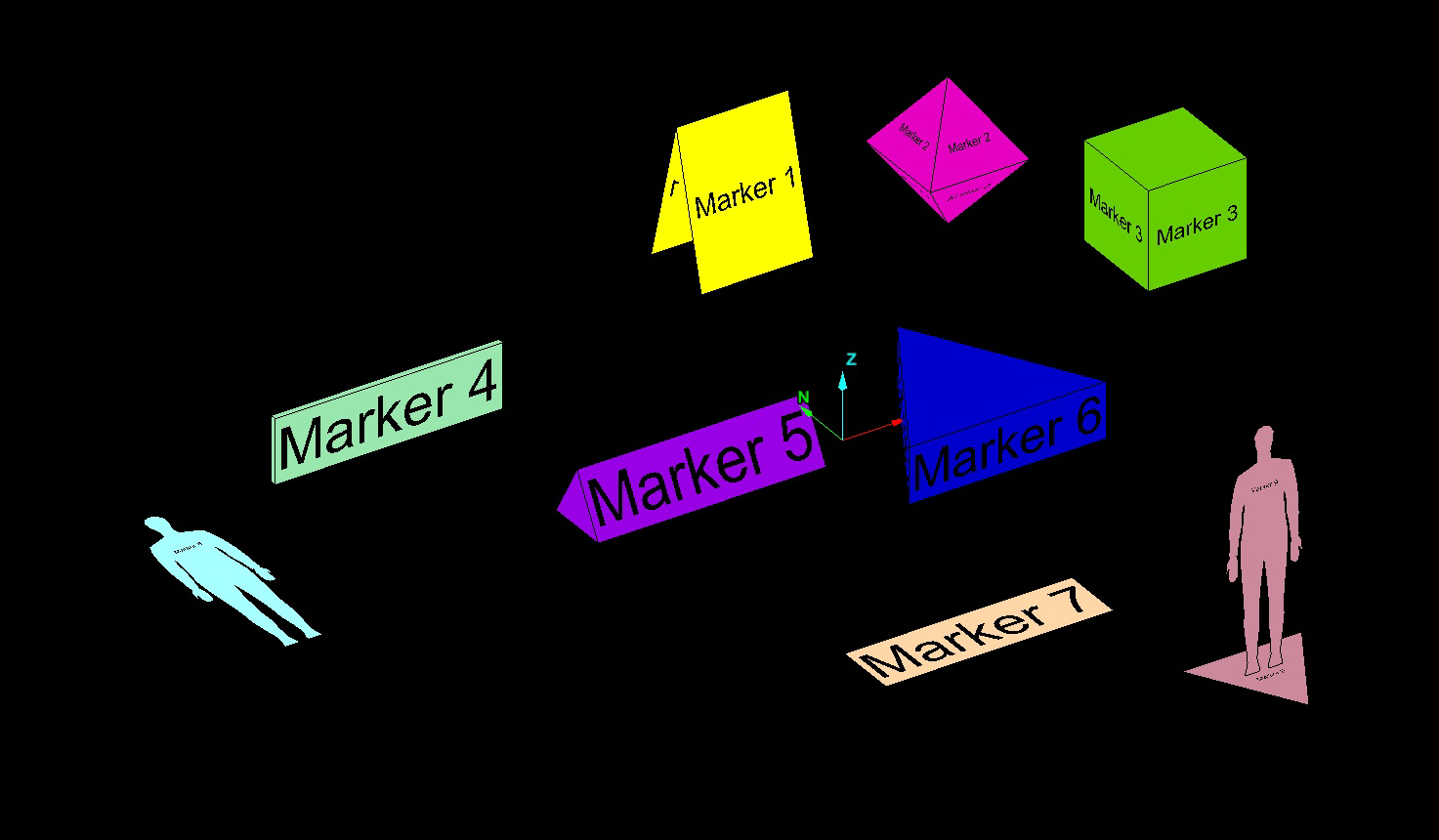
Choose the desired shape for the marker:
-
Marker
-
Diamond
-
Cube
-
Vertical Frame
-
A-frame sign
-
Three-sided sign
-
Horizontal sign
-
Prone human
-
Upright human
-
-
Ticking Fade to 2D text when zoomed out ensures that the marker's location is always visible, by displaying the marker as 2D text when the object itself is no longer visible.
-
Select the Colour for the name of the marker, as well as its size and height.
-
Close the panel the apply the changes.
-
Select OK or Apply to complete the process.
The marker is saved in the cad container by default.
Generally, the attachments can be any type of file. These attachments can also be opened and then viewed (provided Windows recognises the file type and has the appropriate viewer installed). The attachments can be added by going to Create > Text > Edit Marker Attachments or right-clicking a marker and selecting Attachments > Edit attachments.
Edit Marker Properties
The Marker properties editor is used to adjust colour, font, size and alignment of markers created.
Markers can have files attached to them. The attachments allow notes, reports, photographs, diagrams and video files to be easily accessed from a marker which creates visual cue within a View window.
-
Create a marker and select it.
-
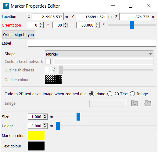
Go to Create > Text > Edit Marker Properties. This will open a new panel.
-
Change the centre point by clicking in the Position fields to activate them, then clicking a new point in the View, or manually entering new coordinates. Right-clicking in these fields gives the option to use the coordinates of the selection centre.
-
Select the Orientation of the marker, or nominate that the sign's face remains perpendicular to the viewer by using Orient sign to you.
-
Change the text to be displayed at the marker location in the Label field if required.
-
Choose the desired shape for the marker.
-
Ticking Fade to 2D text when zoomed out ensures that the marker's location is always visible, by displaying the marker as 2D text when the object itself is no longer visible.
-
Select the Colour for the name of the marker, as well as its size and height.
-
Close the panel to apply the changes.
Generally, the attachments can be any type of file. These attachments can also be opened and then viewed (provided Windows recognises the file type and has the appropriate viewer installed). The attachments can be added by right-clicking a marker and selecting Attachments > Edit.
Edit Marker Attachments
This command allows you to edit attachments associated with markers .
Attachments can be any sort of file, but generally include reports, photographs, diagrams and videos. The attachments can be added or removed from the marker object , as well as opened and viewed (provided Windows recognises the file type and has an appropriate viewer installed).
-
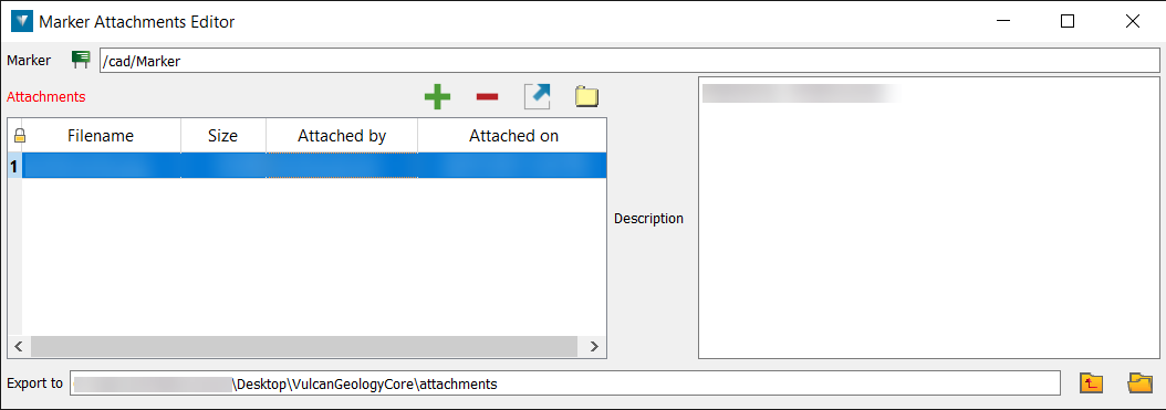
Go to Create > Text > Edit Marker attachments. The Edit Marker Attachments panel will open. The panel displays the Marker name at the top, the file details of any files that have been added, a text box to the right displaying the name of the person who attached the file and some nominated file details. Below these boxes is the Export to location for exporting files that have been added.
-
Choose a desired action from the following functions.
-
Add — Add a file as an attachment to the marker object. A separate panel will open allowing you to navigate to, and select your file(s). You can also some text as a description for the file.
-
Remove — Remove the selected file(s) from the marker object.
-
Export — Export and save the selected file(s) to the location nominated in Export to text box.
-
Open — Open the selected file(s), providing Windows recognises the file type and has the appropriate viewer installed.
-
The attachments can also be added by right-clicking a marker and selecting Attachments > Details or viewed by directly clicking on the attached file name.
