Transform
The following table describes the tools in the Transform section of the Edit tab.
| Tool | Description |
| Translate | Translates (shift) data in any of the three axes (X, Y, Z). |
| Rotate | Rotates data around the three axes. |
| Scale | Scales objects. |
Translate
Translate data is used to translate (move) data in any of the three axes (X, Y, Z). Note: Drillholes can not be transformed using these tools.
- Select Edit > Transform > Translate or click the icon.

- Select a translate direction from the drop-down menu. By default, specify two points (From and To) to define a vector.
- Two Points: Specify coordinates to translate the object From and To.

- Two Points and Distance: Specify coordinates to translate the object From and To to specify an orientation, and a Distance to translate by.

- Facet and Distance: Select a facet on a triangulation by clicking in the View window, then enter a Distance to translate by. The translate direction will be normal to the facet.

- Axis Aligned and Distance: Select an axis (x, y, z) and enter a Distance to translate by.

- Bearing, inclination and distance: Enter a Bearing (0-360 degrees), an Inclination (+ or - 90 degrees) and a Distance.

- Action plane axis and distance: Toggle the radio button to the desired alignment and enter a distance, or use the up/down arrows or slider bar.

- Enter the required information into the fields. Coordinate fields can be populated by clicking in the View window. Note: Right-clicking in a field will display a context menu. With an object selected, the coordinates of the Selection centre can be chosen.
- Select the object to be translated.
- Click the Translate forward or Translate backward buttons to translate.
Select Translate a copy to duplicate the original object and translate the new copy each time Translate forward or Translate backward is selected.
Rotate
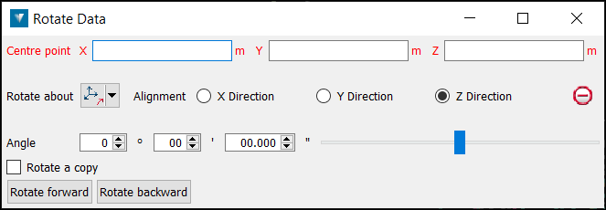
Rotate data is used to rotate data around the three axes (X, Y, Z) or around an arbitrary axis. Note: Drillholes can not be transformed using these tools.
- Select Edit > Transform > Rotate or click the icon.

- Select a Centre point of rotation. The centre of rotation can be clicked on in the View window or entered.
Tip: Right-clicking on Centre point will display a context menu. With an object selected, the coordinates of the selection centre can be chosen from the context menu.
- Select the method of defining the rotation axis from the Rotate about drop-down list.
- Two points: Rotate around an axis defined by two points.
- Facet: Rotate around an axis perpendicular to a facet.
- Axis aligned: Rotate about X, Y or Z.
- Bearing and inclination: Rotate about an axis defined by a bearing and inclination.
- Action plane axis: Rotate about an axis defined in relation to the action plane orientation.
- Select the object to be rotated.
- Enter an Angle to rotate and use the Rotate forward and Rotate backward buttons to rotate clockwise and anti-clockwise.
Select Rotate a copy to duplicate the original object and rotate the new copy each time Rotate forward or Rotate backward is selected.
Scale
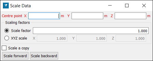
data allows data to be scaled in axial directions. Note: Drillholes can not be transformed using these tools.
- Select Edit > Transform > Scale.

- Select a Centre point reference about which the object is scaled.
Tip: Right-click in a Centre point field will display a context menu. With an object selected, the coordinates of the selection centre can be chosen from the context menu.
- Enter a Scale factor or factors for each of the X, Y and Z axes.
- Select Scale forward to increase the data size by the scale factor, or Scale backward to decrease.
Select Scale a copy to duplicate the original object and scale the new copy each time Scale forward or Scale backward is selected.
The effect of the scaling on the data is illustrated via the translucent green cube, with the attached red arrows demonstrating the relative size the box (the data) will be scaled.
