Ellipsoids
Ellipsoids are objects used to influence the shape of an implicit model.
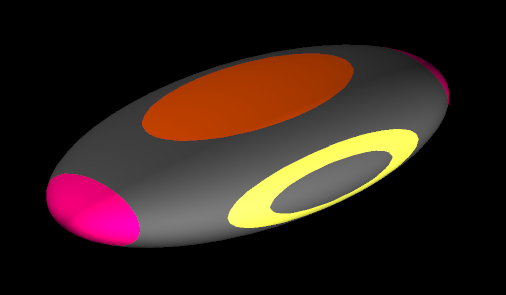
An ellipsoid defines three mutually perpendicular axes, each of which expresses a direction and a relative magnitude. By orienting ellipsoids in space, you can indicate the trend or anisotropy of a geological domain.
The axes of an ellipsoid are named major, semi-major and minor. Generally the direction of the major axis should be used to indicate the trend direction of the structure, but the names are essentially arbitrary.
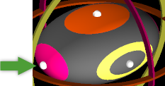
The visualisation of an ellipsoid uses three colours to represent each axis. The “forward” direction of each axis is indicated by solid colour at one end of the ellipsoid, while the “backwards” direction is indicated by a ring shape in the same colour.
Creating an ellipsoid
To create a single ellipsoid:
-
Set the centre of rotation at the initial location you want the ellipsoid to appear. You can move the ellipsoid in a later step before finalising creation.
 Expand for detailed instructions on how to set the centre of rotation.
To set the centre of rotation:
-
Click
 on the view window toolbar. Alternatively, navigate to Create > Manipulation > Set Centre of Rotation.
 -
Pick the location in the view where you want the centre of rotation.
-
-
On the ribbon, navigate to Modelling > Implicit Modelling >
 Ellipsoid.
The Ellipsoid panel appears and an ellipsoid appears in the view at the centre of rotation.
-
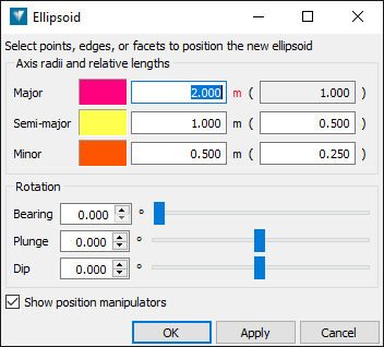
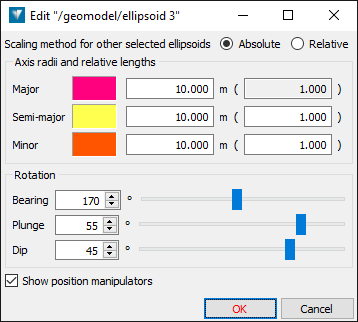
Configure the ellipsoid parameters.
You can configure the ellipsoid by changing values in the panel, or by using the ellipsoid’s dynamic manipulators in the view.
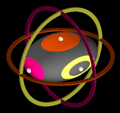
Clear the Show position manipulators checkbox to hide the position manipulators. Only the ellipsoid and its parametric manipulators will be shown in the view.
Axis radii
The axis radii define the size and shape of the ellipsoid. The absolute values of the radii only affect the size of the visualisation; it is the relative lengths that affect the shape, which in turn is what affects the model.
To change the axis radii, either:
-
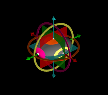
In the view, use the middle mouse button to drag the radius manipulator (white sphere) for the axis you wish to change.
-
In the panel, enter values in the fields next to Major, Semi-major and Minor. The values to right in parentheses are the relative lengths scaled such that the length of the major axis is exactly 1.
Axis rotation
An ellipsoid can be given any orientation in space. Orientation is defined by bearing (rotation around the Z axis), plunge (rotation around the East axis after the bearing is applied) and dip (rotation around the North axis after bearing and plunge are applied).
To change the ellipsoid’s orientation, either:
-
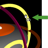
In the view, use the middle mouse button to drag the rotation manipulator (orbital ring) for the axis around which you wish to rotate.
-
In the view, use the middle mouse button to drag the ellipsoid itself. The ellipsoid is not constrained to rotate around any particular axis.
-
In the panel, change the Bearing, Plunge, or Dip values on the panel by entering exact values, or using the sliders.
Ellipsoid position
You can move the ellipsoid within the view in the following ways
-
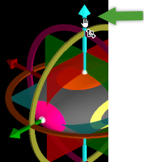
Use the middle mouse button to drag an axis position manipulator (arrow). The ellipsoid will be translated up or down the axis.
-
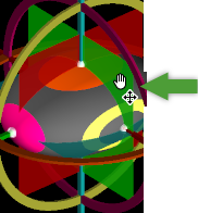
Use the middle mouse button to drag an axis plane manipulator (square). The ellipsoid will be constrained to move anywhere on that plane.
-
Set a new centre of rotation. The ellipsoid will move to that location.
-
Make a primitive selection of points, edges or facets. The ellipsoid will move to the centroid of the selected primitives.
-
-
Press OK or Apply to create the ellipsoid.
The ellipsoid
 is created and saved into the geomodel standard container
  .
.
Editing Ellipsoids
To edit an existing ellipsoid, right click on it in a view window and select ![]() Edit... from the context menu.
Edit... from the context menu.
Edit the ellipsoid’s parameters and position using the same methods described above.
Editing multiple ellipsoids
You can edit the size and shape of multiple ellipsoids simultaneously. You can choose to apply size changes so that either the absolute or the relative axis lengths are applied.
To edit multiple ellipsoids:
-
Select the ellipsoids you wish to edit.
-
Right click on one of the ellipsoids in a view window and select
Edit... from the context menu. -
For Scaling method for other selected ellipsoids, choose either:
-
Absolute — Choose this method to give all the selected ellipsoids the same size and shape.
-
Relative — Choose this method to give all the selected ellipsoids the same shape, but maintain their own relative size by fixing the major axis length.
-
Note: Changes made to the orientation or position of the ellipsoid you are editing will only apply to that single ellipsoid.