Surfaces
The following table describes the tools in the Surfaces section of the Query and Filter tab.
| Tool | Description |
| Surface Volume | Calculates the volume between two surfaces or to a defined level. |
| Closed Solid Volume | Calculates the volume of a closed solid. |
| Differential Solid Volume | Calculates changes in underground void volumes. |
| Boundaries | Creates a boundary polygon around the selected surface. |
| Check Validity | Checks for problems with the structure of triangulation surfaces. |
Surface Volume
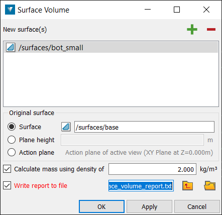
Surface volume (Alt+V) calculates the volume enclosed by two surfaces ![]() or the volume from one surface to a plane at a fixed elevation.
or the volume from one surface to a plane at a fixed elevation.
-
Select Query and Filter > Surfaces > Volume > Surface volume.
-
Drag and drop the triangulation to be measured into the New surface field.
-
Specify either an existing Surface to calculate a volume between or a Plane height to use. Note that the volume is only computed in the areas where the two surfaces overlap, when viewed from above or in the Z direction.
The Original surface should be a base model.
If a plane height is being used, a Reduced Level (RL) can be typed in manually or a point can be selected directly off the model in the View window. A horizontal plane at that RL will be created.
-
Volume calculations can be reported in units of mass or density. To report in density, select the Calculate mass using density of check-box and enter a density.
-
Tick Write report to file to save the results to a text file. Alternatively, this information can be seen in the Report window and copied and pasted into a document.
Closed Solid Volume
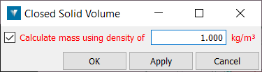
Closed solid volume (Alt+B) measures the volume of a triangulation solid .
-
Select the required triangulation.
-
Select Query and Filter > Surfaces > Volume Closed solid volume or right-click a surface and select Query > Closed Solid Volume.
-
Specify the units to be used to calculate the mass.
The volume of the solid is reported in the Report window.
Differential Solid Volume
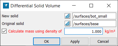
Differential solid volume (Alt+J) measures the volume difference between two triangulation solids ![]() .
.
-
Select Surface > Differential solid volume.
-
Drag and drop the new triangulation into the New surface field using the middle mouse button.
-
Drag and drop the original triangulation into the Original surface field using the middle mouse button.
-
Specify the density to be used to calculate the mass.
Both triangulations are checked for inconsistencies and the volume of each solid is calculated and reported in the Report window in terms of volume difference, cut and fill.

Boundaries
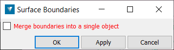
Creates a boundary polygon around the selected triangulation surface.
-
Select the required triangulation.
-
Select Query and Filter > Surfaces > Boundary
-
Use the Create as a single object tickbox to specify whether the output polygons should be created as a single object, or as separate objects where discontinuities exist.
-
Boundary polygons are stored in the cad container.
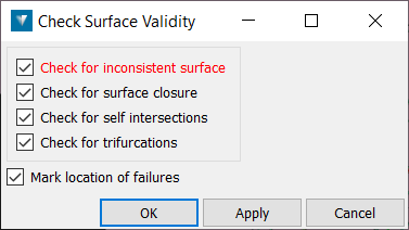
Check Validity
Check validity checks for any problems with the structure of triangulations, such as holes or self-intersecting triangles.
-
Select a triangulation .
-
Select Query and Filter > Surfaces > Check validity or right-click the surface and select Query > Surface Validity.
-
Check for inconsistent surface checks that all triangles are pointing in the same direction (if not, this can lead to problems with calculating volumes and creating fusions).
-
Check for surface closure checks for boundary edges. This is only applicable to closed solid triangulations. Untick this for all other surfaces.
-
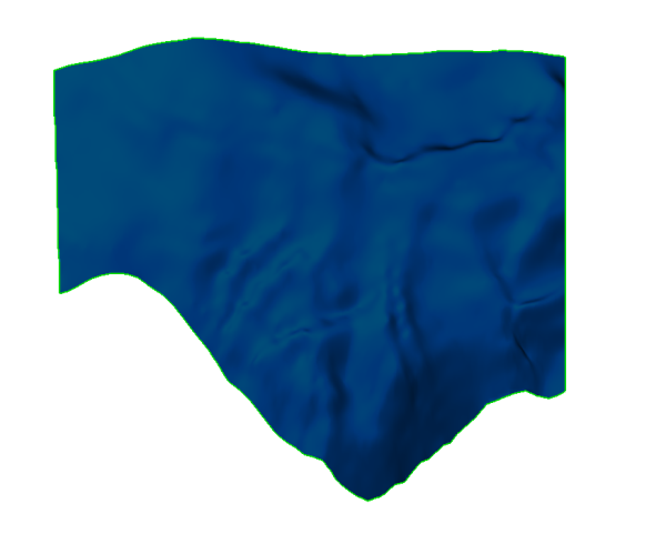
Check for self intersections checks for self intersecting triangles on the surface, as shown below.

-
Check for trifurcations checks for and finds any edges with more than two facets sharing the same edge on a surface.
-
Select Mark location of failures to create objects in the cad container for the selected checks, enabling identification of errors.
-
Select OK.
-
Drag and drop any objects created in the cad container onto the triangulation View window to display any errors found.
-
To repair any errors found, zoom into the error and display the triangulation in wireframe.
-
Using point selection mode, select a corner point on the triangle and press Delete.
-
To fill the hole created, select Fill holes.
-
Repeat this procedure for all errors found.